RFID card reader designed with card reader chip FM1715SL
Abstract: According to the vehicle identification system's identification requirements, a RFID chip reader based on domestic chips is proposed. The data interface is designed as an ISO14443 TypeB device. Under the premise of meeting security and confidentiality, it is easy to use and convenient and efficient. The large-scale in-vehicle application verifies the reliability of the solution.
This article refers to the address: http://
introduction
A vehicle management system has a clear need for the identification of vehicle users. In the case of strong vehicle interference, it is required to accurately and quickly identify vehicle user information. Combined with the specific use of the vehicle, comparing the IC card, RF card, ID card, etc., the vehicle installed electronic tag reader and passive electronic tag identification scheme, and finally determined the passive RFID (Radio Frequency Identification) scheme. RFID is a non-contact automatic identification technology. The target object is automatically identified by the RF signal and the relevant data is obtained. The identification process does not require manual intervention, and can work in various harsh environments, and the operation is quick and convenient. Depending on the frequency band, RFID is divided into low frequency and high frequency systems. Low-frequency short-range RFID systems mainly have 125 kHz and 13.56
The MHz band; high frequency RFID systems are mainly 915 MHz, 2.45 GHz and 5.8 GHz. Passive electronic tags (RFID cards), also called passive tags, receive RF signals after entering the recognition range of the card reader, convert some of the RF energy into DC power, and then send the information data stored in the chip to the card reader. Passive electronic tags are low in cost, have a long service life, are small in size, and have close reading and writing distances.
In the application, the card reader is installed as a sensor of the vehicle monitoring terminal on the vehicle, and recognizes different vehicle users by reading different RFID cards, including the second generation ID card, and completes identification, time statistics, attendance punching. And alarm reminders and other functions.
1 card reader overall design
In order to improve information security, the following design ideas are adopted in the overall design: component selection is only preferred in mainland China design and manufacturing companies; communication protocol adopts safer ISO14443 Type B protocol (the agreement is the same as China's second generation ID card). Types of cards are used in buses, cafeterias, shopping malls, clubs, etc., but TypeB cards have higher security than TypeA cards. When receiving signals, the internal logic and software work of the chip will not stop due to energy loss. Higher communication speed and stronger anti-interference ability ensure data security.
The card reader adopts the universal contactless card reader chip FM1715SL as the core, and adopts the microcontroller HR7P90H of Shanghai Haier Integrated Circuit Co., Ltd. as the processor. Other key modules include unit modules such as interactive interface, power management and RFID radio frequency. The overall block diagram of the RFID card reader is shown in Figure 1.
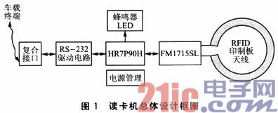
As the main device, the vehicle-mounted terminal supplies power to the card reader through the data-power composite interface for data communication. The power management module outputs the voltage required by the card reader; the RS-232 driver circuit completes the electronic conversion of the serial port communication; the HRTP90H performs bidirectional data communication with the FM1715SL through the SPI port to realize the identification of the RFID card; the antenna of the FM1715SL adopts the printed circuit board antenna, further Reduce cost and improve productivity; HR7P90H realizes sound and light reminder through buzzer and LED according to information such as vehicle terminal and card status.
The card reader can read the global unique ID number of the second generation ID card, which can omit the purchase of the card, and the vehicle user's ID card can be used as the identification card at the same time.
2 system hardware design
The system hardware mainly includes the interface circuit of the card reader chip and the controller, the power supply circuit, the clock circuit and the matching circuit.
2.1 RFID card chip
Considering the development difficulty, device maturity, production supply and other aspects, we chose FM1715SL designed by Shanghai Fudan Microelectronics Co., Ltd., which is a special chip for contactless card reader based on ISO14443 standard, supporting TypeA at 13.56 MHz frequency. Two types of contactless communication protocols and TypeB, as well as a variety of encryption algorithms. The FM1715SL has a highly integrated analog circuit that requires only a small amount of peripheral circuitry; an operating distance of up to 10 cm; supports ISO14443 TypeA and TypeB protocols with built-in encryption unit. The circuit design of FM1715SL is shown in Figure 2.
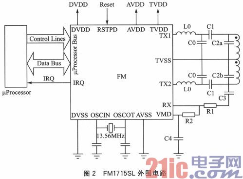
Interface circuit: The data bus of FM1715SL is a standard 4-wire SPI interface. The FM1715SL acts as a slave device, and the microprocessor completes communication control through the SPI bus and FM1715SL output interrupt.
Transmitting circuit: The reference clock of the FM1715SL codec is 13.56MHz, which is generated by the crystal oscillator and its driving circuit. Transmitted from the TX1 and TX2 pins is a modulated 13.56MHz carrier signal with a higher harmonic content in addition to 13.56 MHz. The filter consisting of L0 and C0 in Figure 2 is used to filter the harmonic power of 13.56 MHz to meet the requirements of the relevant EMC regulations.
Receiving circuit: The receiving circuit of the FM1715SL uses the response signal of the RFID card to modulate to the double sideband of the subcarrier for communication. The FM1715SL outputs VMD as the RX pin bias voltage and uses filter C4 for filter regulation; resistors R1 and R2 form the voltage divider circuit between RX and VMD.
Antenna design: The antenna is an important part of the RFID card reader. The performance of the card reader has a direct relationship with the parameters of the antenna. Antenna modeling has a direct connection model and a 50 Ω impedance matching model. Since the card and antenna are designed to be less than 5 cm in direct distance, the antenna can be designed onto the PCB using a simple, low-cost direct connection model. The antenna model is shown in Figure 3.
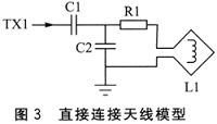
During card reader and card communication, the antenna is used to generate magnetic flux that can transmit and receive radio frequency signals. Magnetic flux is used to power the RFID card and transfer information between the card reader and the card. Therefore, the current of the antenna coil is designed to be the largest to generate the maximum magnetic flux. 13.56 MHz belongs to the short-wave frequency band, so a small loop antenna can be used, which has a square shape, a circular shape, an elliptical shape, a triangular shape, etc. The design uses the rectangular antenna shown in FIG. C1 completes the 50 Ω matching at the transmitting end to improve the energy transmission efficiency; C2 and the equivalent inductance L1 of the antenna constitute a 13.56 MHz resonant network; R1 is used to adjust the quality factor Q of the antenna. In the antenna design, Q is a very important parameter. If Q is too small, there will be blind spots in the card reading range, which will affect the stability and reliability of data communication. If Q is too large, the card reading distance will be shortened. Q is generally 35. In order to improve production consistency and reduce the difficulty of debugging, the PCB adopts multi-layer board design and finely designs the inductance and impedance of the rectangular antenna through laminated impedance control. At the same time, the resistance of the analog circuit adopts the 1% precision mounting model, and the capacitance is low. Temperature coefficient, low temperature drift, 1% accuracy, chip capacitance of NPO media.
2.2 Microcontroller
The HR7P90H is Haier's high-performance 8-bit reduced instruction set microcontroller with a rich set of on-chip peripherals. Among them, the high-speed asynchronous transceiver UART realizes communication with the vehicle terminal; the 4-channel LED, the 1-way buzzer control and the 1-channel SPI interface are simulated through the I/O port; the built-in protection circuit satisfies the industrial-grade ESD (Electrostatic Discharge) ) and EFT (Electri cal Fast Transientburst) standards, very suitable for industrial control and automotive electronics. The HR7P90H has a built-in 16 MHz oscillator and power-on reset circuit. The SOP28's small chip package greatly reduces peripheral circuitry and provides more board area for the RF and antenna circuit design of the FM1715SL. The HR7P90H supports In-System Programming (ISP) and In-Circuit Debugging (ICD). The circuit is designed with these two interfaces to facilitate development, debugging and mass production.
2.3 Industrial Design
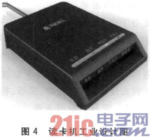
The industrial design fully considers the special characteristics of high temperature and vibration of the vehicle environment, and takes into account the convenience of the user. The card reader is designed as a contact card slot to facilitate the fixing of the card. On the one hand, the card to the antenna is shortened, the design difficulty of the printed circuit board antenna is reduced, and the appearance size of the card reader is also reduced. The card reader is only slightly larger than the card and is easier to install. The material is selected from flame retardant ABS (Acrylonitrile Butadiene Styrene), and multiple nylon beadings are designed inside the card slot to further improve the stability of the card in the vehicle environment. The industrial design of the card reader is shown in Figure 4.
3 identification software design
The main function of the recognition software is to automatically detect various cards entering the recognition range, complete communication with the vehicle terminal, and set related indicators and buzzers according to the data content and card information.
Software programming is done using Haier's integrated development environment HR-IDE tool. HR-IDE supports C language editing, cross-compilation, link debugging and simulation. Considering the scale and complexity of software code, development and debugging use low-cost ICD. Emulator. Identification software development uses an interrupt-driven data stream processing architecture. The software flow diagram is shown in Figure 5.
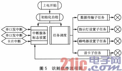
The recognition software mainly consists of an interrupt service program, task scheduling and various subtask handlers. The interrupt source of the whole software includes serial transceiver communication interrupt, FM1715SL external interrupt and soft interrupt triggered by each subtask. Each interrupt service program is simple and short, can quickly complete the real-time work such as setting the flag to read data, release the processor resources to complete various task processing; the task scheduling module performs sub-task scheduling according to the set flag, each sub-task Upon completion, the flag is cleared and returned; the subtask can also set a flag to trigger scheduling of other subtasks.
For example, after the card reading task completes the card reading, it will trigger the interrupt and set the flag; the transmission subtask will send the card number to the vehicle terminal; if the card number is invalid or the card cannot be read periodically, the transmission subtask will also be triggered, and the vehicle terminal will send the light up. The instruction of the invalid card" indicator, the serial port interrupt is triggered, the indicator setting subtask will be called, and the "invalid card" indicator lights up.
The HR7P90H only has 2 KB of SRAM. If the software architecture is RTOS, it is difficult to implement. With the serial multi-function architecture, real-time performance, reliability, and scalability cannot be guaranteed, and debugging is difficult.
Through reasonable division of data transmission and task processing, data reading is interrupt driven, data processing tasks are uniformly scheduled through flags, data reading and data processing are stripped, which satisfies the requirements of high real-time multi-data processing. The entire software architecture is clear and concise, the coding design is simple, and the debugging and maintenance are less difficult.
Conclusion
The card reader has been used as a sensor for an in-vehicle terminal and has been installed in series on the vehicle after various test tests. The work is stable, reliable, safe, and low-cost, and can read the RFID card conforming to the ISO14443 standard Type B type including the second-generation ID card.
Qunsuo aims at providing our customers high qualified Industrial Rugged Pda. In order to meet customers using environment, our PDAs all pass IP65 certification. With the stable quality of our Handheld Android Pda, we gain many reliable customers, help many customers provide IT solutions. If you are also looking for reliable PDA manufacturer partner, Qunsuo will be your good choice. Welcome to contact us for more details!

Industrial Rugged Pda
Android Pda Europe,Pda With Desktop Charger,Rugged Handheld Pda Honeywell,Handheld Barcode Scanner Pda
Shenzhen Qunsuo Technology Co., Ltd , https://www.qsprinter.com