Design of universal smart charger for electric bicycle
This article refers to the address: http://
0 PrefaceWith the rising price of oil and the increasing awareness of environmental protection, electric bicycles are increasingly favored by consumers because of their low price, environmental protection, and safe and convenient use. One of the important parameters for evaluating the quality of an electric bicycle is the service life of its Battery. The charging process of the battery has the greatest impact on its life. Studies have shown that overcharging can cause the battery to heat up and the electrolyte to lose water; while insufficient charging can make the chemical reaction in the battery insufficient, and long-term charging will cause the battery capacity to drop. It can be seen that the performance of the charger directly affects the use effect and service life of the battery. At present, the main disadvantage of the charger on the market is that the first is not to obtain the sampling signal directly from the secondary winding, so the voltage regulation effect is not ideal; the second is that the output current and voltage adjustment range is narrow, so it is only suitable for a fixed load. To this end, this paper introduces a design scheme of a universal smart charger with a single chip as a Controller. The device can intelligently adjust the charging voltage and the charging current according to the charging characteristics of the battery or the state of charge monitored in real time, and has a wide adjustment range and protection functions such as overcurrent, overvoltage and overtemperature.
1 system structure
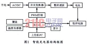
The structure of this smart charger is shown in Figure 1. The system is mainly composed of a power conversion circuit, a sampling circuit, a microprocessor, a pulse width modulator, a keyboard, a display and a temperature sensor, and is a closed-loop intelligent charging system.
2 hardware circuit
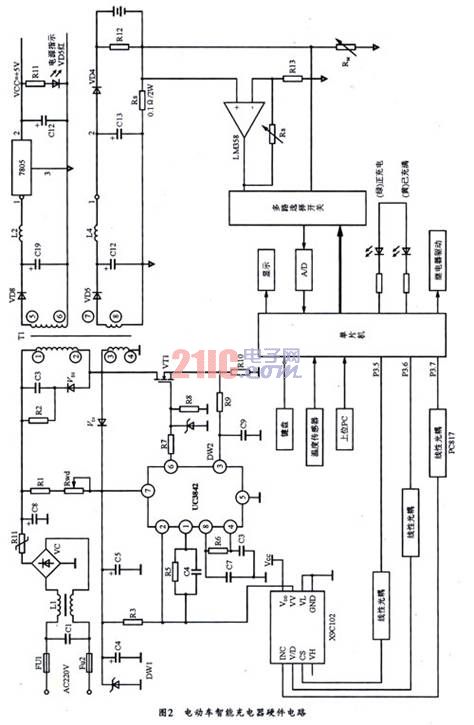
The hardware circuit of the intelligent charger is shown in Figure 2. The whole circuit is divided into three parts: the switching power supply part, the control circuit mainly based on single chip microcomputer and the pulse width modulation circuit with UC3842 as the core.
2.1 switching power supply design
This design uses a current-controlled pulse width modulation method. The whole working process is to convert the AC input into DC high voltage after being filtered and rectified, and then the high frequency rectangular voltage is obtained by the switching tube chopping and high frequency transformer stepping down, and finally the required DC output voltage is obtained through output rectification filtering. The system requires a switching power supply with an AC input voltage range of 90 to 270 V, which can simultaneously output +5 V (as part of the control supply) and 12 to 60 V (main circuit). The output current is 1 to 3 A.
2.2 MCU control circuit design
The MCU control circuit is mainly composed of single chip microcomputer AT89S52, ADC (TLC0832), multi-way selector switch (CD4051), digital potentiometer (X9C102), digital temperature sensor DSl8820, sampling resistor R s and R w , 2×4 keyboard, liquid crystal display (CONl6 ) and other components.
This part should be designed according to the battery model parameters, through the keyboard design corresponding charging current, charging voltage and charging time, when the circuit is connected to the battery, the charging process begins, after which the microcontroller detects the battery voltage through the sampling resistor RM If the battery is detected to be transitional discharge, the voltage is lower than the normal range. Then, in order to avoid damage to the battery caused by excessive charging current, a stable small current charging should be applied to the battery (set to 1/5 in this design program). At the same time, the MCU starts timing, after which the MCU will continue The battery voltage and the charging current are detected and displayed on the liquid crystal screen. As the charging progresses, the battery voltage continuously rises. When the battery is raised to the normal range, the single chip microcomputer can adjust the output voltage by controlling the digital potentiometer, thereby transferring the high current constant current. Charging (that is, setting the current) mode. After that, the MCU keeps detecting the battery voltage continuously. When the voltage reaches the set value, the MCU issues a command to increase the resistance of the digital potentiometer and reduce it by pulse width modulation. The output voltage. Therefore, the charging current is reduced. When the charging current is reduced to a set current of 1/5, the battery is switched to trickle charging, and finally the power is turned off when the charging time is reached, thus avoiding the battery temperature rising too fast or serious. Polarization affects the quality of the charge and improves the service life of the battery. When it is detected that the battery voltage, charging current and temperature exceed 1/10 times of the set value (set by the program), the MCU immediately outputs an alarm signal alarm. At the same time, the relay is activated and the total power supply is cut off to improve the safety and reliability of charging.
The display can be used to display the battery voltage, charging current, charged time and battery temperature sampled by the microcontroller in real time. The keyboard is used to set the charging voltage (charging limit voltage), constant current charging current (limit charging current) and charging time. The single-chip microcomputer in the circuit can be connected to the host computer through the serial port RS232 for storing data and setting the charging parameter of the virtual display. When the charging current is detected to be zero, the microcontroller goes to sleep. When it is detected that the charging current is not zero, the microcontroller is activated.
2.3 Pwm Controller design
The PW M controller part is based on UC3842. The UC3842 contains a 5.0 V reference voltage regulator, a high gain error amplifier, and a pulse width comparator that controls the drivers in the chip. The driver can provide 25 mA of output current. The NOSFET regulation tube can be driven directly to adjust the charger's output voltage and current. Since the driver has overcurrent and overvoltage protection at the same time, the working power supply voltage can be 8 to 40 V, and the starting current is less than 1 mA, and the operating temperature is 0 to 70 ° C, so it is an ideal new pulse width modulator.
The PWM controller is started by R 1 , R w . Providing the UC3842 starting voltage, wait until the work, the auxiliary winding 3,4 of the terminal voltage by the rectifier D 1, C 4, C 5 filter, regulator obtained after DW 1 16 V DC voltage applied to pin 7 along the UC38427 Power is supplied to it, and the other is divided by R3 and digital potentiometer X9C102 and added to pin 2 of UC3842. Used as an input signal for pulse width modulation. Generally, in the design of this type of power supply, the output voltage sampling can be connected to the supply voltage of the UC3842. In order to reflect the change of output voltage, this design does not add a voltage regulator tube, but this will make the working voltage of UC3842 unstable and the output harmonic component increase. In order to overcome this deficiency, the power supply voltage of UC3842 in this design adopts the winding ends of 3 and 4 After the voltage is separately rectified, filtered, and stabilized, it provides a stable voltage of 16 V to the UC3842 chip. The charging voltage is adjusted by sampling the battery voltage through the outer loop voltage sampling circuit R 12 and R M , and then selecting by multiple electronic switches, MD conversion, and processing by the single chip, and then feeding the digital potentiometer to control the effective resistance of the digital potentiometer. . Thus indirectly control the voltage of the 2 pin of the UC3842, and then control the pulse duty cycle to change the charging voltage.
When the output voltage of the charger is high, the voltage of the 2-pin fed back to the UC3842 also rises (beyond the reference voltage of 2.5 V), the pulse duty ratio of the drive signal is reduced, and the output voltage is lowered, thereby achieving the purpose of voltage regulation. The charging current is mainly adjusted by first sampling the charging current through the outer loop current sampling resistor R s and LM358 (using R1 to adjust the amplification factor), multi-channel electronic switch selection, MD conversion, and then sent to the MCU for processing, and then adjusting the resistance of the digital potentiometer. value. The adjustment process is similar to voltage regulation. In fact, current regulation is also achieved by voltage regulation.
2.4. Protection circuit design
When overcurrent or short circuit, the voltage at both ends of the inner ring 10 sampling resistor R increases. When the voltage of pin 3 exceeds 1 volt, the internal modulation of UC3842 can stop the pulse width output, the switch is turned off, and the output voltage and current are both 0, thus protecting the power supply. When overvoltage, DW 1 and DW 2 will break down and short circuit, which will also cause overcurrent protection. DW 2 can be used to protect FET and UC3842. When an undervoltage occurs, that is, when the voltage of pin 7 of UC3842 falls below 10 V, the UC3842 will start the undervoltage lockout circuit and turn off the switch controller. This feedback adjustment of the inner loop is to adjust the pulse width by detecting the inner loop current when the output voltage has not changed, (feedforward control), thereby accelerating the dynamic response speed of the converter to the abnormal situation. In order to protect more quickly and effectively. Of course, the sampling of the outer loop current and voltage (R s , R w ) can also be used to protect the abnormal situation by the regulation of the single-chip microcomputer, but the response speed is 5 to 10 power-frequency cycles slower than the inner loop. Therefore, the outer loop The sampling mainly adjusts the charging current and the charging voltage, which doubles as secondary protection, while the inner ring sampling is the main one. It is a one-time protection, and the double-ring protection method is more safe and reliable.
3 software design
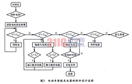
In the initial stage of the program, the first step is to initialize the microcontroller, that is, to set different charging parameters according to different batteries, and select different charging strategies. Then it is judged whether the battery is connected correctly, and according to the battery voltage value, it is judged which charging phase should be entered (ie, small current pre-charging, high-current constant current charging or constant voltage trickle charging mode). In the precharge phase, the charging voltage should be reduced. In the constant current mode, the charging current should be continuously detected to reach a constant current (such as 1.8 A). If it is less than 1.8 A, the voltage across the battery should be raised to 1.8 A. The above adjustment process can be proportional control. After the voltage across the battery reaches the set value, the system enters trickle charge mode. The program flow of the charger is shown in Figure 3. In FIG. 3, I s is a set charging current (ie, a constant current charging current), U min is a discharge limit voltage of the battery, and U max is a charging limit voltage of the battery.
4 application test
This design selects the 36 V/12 Ah lead-acid battery commonly used in electric bicycles as the test object. The constant voltage charging voltage is set to 43 V, and the constant current charging current Is is 1.8 A. At the beginning, as the charging progresses, The charging current is almost maintained at 1.8 A, but the battery voltage is constantly rising, after charging for 3 hours. The voltage rise slows down; after charging for 4 hours, the charging voltage is close to 43 V; then the voltage rises more slowly. And the charging drops faster. When charging to 43 V, the charger automatically stops. From the test data, the design achieves constant current fast charge, constant voltage charge, and full self-shutdown design requirements.
5 Conclusion
The over-discharge pre-charge, constant-current fast charge, constant-voltage charge and intelligent control charging scheme designed in this paper can solve the problems of over-charging, insufficient charging and heat in the charging process of electric bicycle batteries. Different charging schemes can be selected according to different batteries. And it is versatile. It can detect and display parameters such as charging current, charging voltage, charging time and battery temperature in real time. Since the circuit has internal and external loop control, it conforms to the optimal control law. It has the functions of over-current, over-voltage and over-temperature protection. At the same time, because UC3842 uses regulated power supply, not only the harmonic pollution is low, but the primary and secondary electrical isolation is safe and reliable. At the same time, it can be controlled by the single-chip microcomputer according to the load condition. It can also work in the skip cycle mode. Therefore, the efficiency of the power supply can be improved.
APPLICATIONS
DELIGHT lighting pole is ideal for pedestrian, street, highway and other general lighting applications. 2m-4m for garden, parks, pedestrian streets. 5m-12m for roads, highway.12m-30m for plazas, airport, seaport, squares
MATERIAL
Q235, Hot-dip galvanized steel, galvanized plating on both of side of pole. Zinc plating 120-130 micron average. Steel anchor bolt with bolts & screws. Hand pole,
SHAPE
Tapered, Square, Octagonal, Hexagonal, Conical, Round
DEMENSION
Top diameter & bottom diameter, thickness customized, while we will provide proposal according to application condition
FINISH
Finishes include hot dip galvanized or painted. Please consult factory for special finishing color and fixture matching options
Street Light Pole,Light Pole,Street Pole,Yard Light Pole
Delight Eco Energy Supplies Co., Ltd. , http://www.cndelight.com