Design and Implementation of Wireless Automatic Measurement and Control System Based on LabVIEW
Aiming at the problem of explosive pressure measurement at the ammunition explosion site, LabVIEW is used as a tool to design a wireless automatic measurement and control system, which is mainly composed of sensor network node, wireless relay station AP and upper computer. The measurement and control system uses LabVIEW as the main control software, and realizes the control, experimental data reading, storage and analysis of wireless sensor network nodes by using graphical programming language and modular design. Through system verification and testing, the system has the ability of data acquisition, wireless transmission and remote control, and is fully capable of handling the explosion pressure measurement in the harsh environment.
In the design process of ammunition, it is necessary to know the relevant data parameters of the ammunition explosion, but the traditional equipment is difficult to meet the needs of these scientific experiments, especially for the harsh experimental sites where humans cannot survive, the acquisition of experimental data is more difficult, development The new instrumentation not only has the problems of long development cycle and low test efficiency, but also greatly increases the test cost. National Instruments Co., Ltd. NI's virtual instrument technology solves the above problems well. The graphical programming language LabVIEW provides many controls similar in appearance to traditional instruments. It is very easy to implement program interface design by means of data flow programming. , writing code and functional implementation, is widely used in aviation, automotive, communications and process control. The wireless measurement and control system designed by LabVIEW realizes the explosion pressure measurement on the explosion site, and solves several key problems such as high development cost, low test efficiency and long system development time. At the same time, the system also has functions of data acquisition, remote control and data analysis. .
1 system overall structural design
The wireless measurement and control system based on LabVIEW is mainly composed of three parts: sensor network node, wireless relay station and host computer. The overall structure is shown in Figure 1. The system sensor network node mainly completes the data acquisition and storage, and imports the collected data into the ARM processor, and the ARM processor controls the data to be sent by the wireless Wi-Fi wireless module to the relay station. In order to ensure that the measurement and control system adapts to wireless long-distance transmission, the wireless AP is selected as the relay station to ensure correct and reliable long-distance transmission of data. At the receiving end, the relay transmits the received data back to the upper computer through the wireless network port. The upper computer is read, processed, displayed, stored and analyzed by the LabVIEW-based measurement and control software.
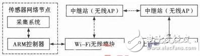
Figure 1 Overall structure of the wireless measurement and control system
The wireless measurement and control system first performs self-test under the control of the LabVIEW software of the host computer. After the self-test is completed, the relevant parameters of the acquisition system in the sensor network node are set by the LabVIEW software, and then the sensor network node is in a state to be triggered. . When the ammunition explodes, the sensor network node is triggered to cause the acquisition system to automatically collect and store the relevant signals. When the sensor network node receives the reading command from the upper computer, the ARM processor in the sensor network node reads out the data stored in the acquisition system and sends it to the Wi-Fi wireless module, and the data is transmitted back to the upper computer through the relay station. . Finally, the LabVIEW software installed on the host computer completes the reading, merging and storage of the data, and can perform related signal processing such as filtering and spectrum analysis on the read back data as needed.
2 system hardware structure design
The hardware part of the wireless measurement and control system based on LabVIEW is mainly composed of sensor, AD converter, FPGA, ARM system, Wi-Fi wireless module, memory FLASH, USB controller FT245, etc. The overall hardware structure is shown in Figure 2.

Figure 2 Overall block diagram of the hardware of the wireless sensor node
The position of A/D converter as the key component of analog-to-digital conversion in the measurement and control system can not be ignored. The AD7492 of AD company is used as the analog-to-digital conversion chip. The resolution of AD7492 is 12 bit, and it is 2.7 V~5.25 V. Operating at voltage, the maximum sampling rate is 3 MB/s, which can handle broadband signals up to 10 MHz. FLASH memory is also very important in the hardware of the sensor node, because all experimental data needs to be stored in the FLASH. On the one hand, the data should be accurately stored and cannot be lost. On the other hand, the stored data should be accurately read. And passed back to the host computer. The NandFlash chip of the measurement and control system uses Samsung's K9K2G08U0M with a capacity of 256 MB, the voltage operates from 2.7 V to 3.6 V, and the page size is 2 kB. The programming and erasing are automatic.
3 system software design
Based on LabVIEW, the PC software of the wireless measurement and control system is mainly developed by NI LabVIEW 9.0. The system software mainly implements the following functions: 1) System parameter configuration, including sampling frequency of the sensor, sampling points and amplification of the signal conditioning module Multiples, etc.; 2) working state detection, that is, working state detection on the selected wireless sensor network node client communication channel; 3) data communication, filtering and spectrum analysis of the received data; 4) testing process The data is stored and the data is read after the test.
The data reading module is the main unit of the software system. The main function is to send the command to execute the collected data to the lower computer, and read and return the collected data. The advantage of LabVIEW is that it has provided the user with a packaged TCPVI function. When using it, you only need to set the listening port of the server-side TCP VI. The client TCP VI only needs to set the corresponding address and remote port to establish a connection with the server. . The block diagram of the server socket communication program in the LabVIEW environment is shown in Figure 3.
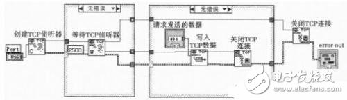
Figure 3 block diagram of Socket communication
According to the Socket technology, the TCP communication process includes: the PC as the server side first listens to the designated port and is in a waiting connection state, and after the data collection end of the client sends a connection request to the port that the server side is listening to, the PC responds to the client first. The terminal sends a data collection command, and then reads the information fed back by the client to confirm the successful handshake, and reads whether the file is the flag of the encrypted file, reads the file data size information, and finally reads the data, and closes the TCP connection after the communication is completed. .
4 experimental results and analysis
As the primary link of the measurement and control system, the data acquisition module has a decisive influence on the realization of the whole system function. Therefore, the correctness of the acquisition module can be verified to ensure the correctness of the subsequent experiments.
4.1 System function verification experiment
Firstly, the parameters of the acquisition module should be set. The parameter setting process is: the upper computer sends the parameter setting instruction, and then the instruction is transmitted to the lower computer through the relay station, and the lower computer adjusts the system to the corresponding working mode according to the prior program setting. Take the No. 1 measurement and control device as an example, set its sampling rate to the third gear, which is 1 Mbps.
In order to verify that the system has correctly entered the corresponding working mode after wireless setting, a sinusoidal signal with a frequency of 1 kHz, a maximum value of 3.1 V and a minimum value of 0.8 V is directly generated by the signal source, and the signal is directly input to the signal. The input end of the conditioning circuit, after the system acquisition is completed, the acquisition result is wirelessly transmitted to the upper computer for display, and the result of the upper computer display is as shown in FIG. 4 .

Figure 4 sine wave acquisition results
4.2 Test results and analysis
In order to further verify the actual working ability of the measurement and control system, the ICP sensor and the measurement and control system were used to perform the explosion pressure measurement experiment on the simulated explosive explosion site. First, the system related parameters are set by wireless, and the system enters the state to be triggered. When the explosive is detonated, the measurement of the explosive transient pressure is completed, and finally the measurement result is wirelessly transmitted back to the computer. Figure 5 shows the experimental results of the explosion pressure measured at the moment of simulated explosive explosion after low-pass filtering.
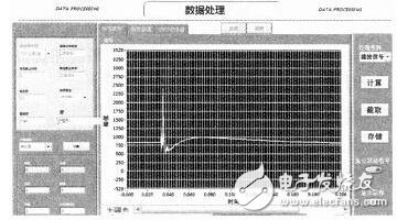
Figure 5 Actual acquisition and processing results of shock wave signals
In Figure 5, the unit of the abscissa is ns, the unit of the ordinate is mV, the minimum amplitude of the sine wave corresponding to the cursor 1 is 795 mV, and the maximum amplitude of the sine wave corresponding to the cursor 0 is 3 102 mV, when the software operation is removed. The error of the cursor is taken. This result is basically consistent with the maximum value set by the signal source of 3.1 V and the minimum value of 0.8 V. The difference between the cursor 0 and the cursor 1 on the horizontal axis can be calculated. The collected sine wave has a period of 1 ms, which coincides with the signal frequency of 1 k which is not set by the signal source. It can be seen from the above experimental results that the measurement and control system can be very accurate from the wireless setting of the parameters, to the data acquisition of the data acquisition module, to the wireless back transmission of the acquisition result, and finally to the upper computer display of the acquisition result. Goodly record the relevant parameters of each state before and after the explosive explosion.
5 Conclusion
Based on the overall structure of the wireless measurement and control system based on LabVIEW, the hardware and software components and design ideas of the system are introduced in detail. The block diagram of the data communication module in the measurement and control system is given. Finally, the data acquisition capability and wireless transmission of the measurement and control system are tested. Control capabilities and the actual application capabilities of the system were verified. The experimental results of the explosion pressure measurement at the explosion site show that the measurement and control system is fully capable of carrying out the tasks of data acquisition, wireless transmission and control in harsh environments.
Factory directly offer the Iphone 5 Battery , all battery we use pure cobalt lithium battery cell, so our Iphone Battery life performance is better than common, after cycle 500 times, the capacity still have 80% at least. It is light weight, high capacity and low impedance. No memory effect, ready to charge and discharge. Our strict QC team to make sure all products are qualified before delivery.
As a professional manufacturer over 7 years experience, Hequanqingnuo technology owns the brand of HQQNUO involved in different kinds of Cell Phone Battery such as IPhone Battery , Huawei Battery , Samsung Battery and other Cell Phone Accessories, such as Iphone Charger Case, QI Car Charger ,Wireless Phone Charger etc.
OEM/ODM and more forms of customization are supported by us.

IPhone 5 Battery
Iphone 5 Battery ,Apple Iphone 5 Battery,Apple 5 Battery,Iphone 5 Extended Battery
Shenzhen Hequanqingnuo Electronic Technology Co., Ltd. , https://www.hqqnbattery.com