Technical solutions to improve the energy efficiency of automotive fieldbus
For traditional passenger cars, the fuel tank is the only real source of energy, so manufacturers are looking to save energy in all automotive systems, including electronic systems, to further improve fuel economy and carbon dioxide (CO2) emissions. As the number of electronic systems added to automobiles continues to increase to enhance vehicle performance and safety, and to provide buyers with attractive new features, the energy savings of each electronic control unit (ECU) in the vehicle is low. It will increase the total fuel consumption.
This article refers to the address: http://
Chip designers have been able to reduce the total energy consumption of the devices they offer by using different technologies and approaches. Combining the functionality of multiple devices in a single system base chip (SBC) and applying different power management strategies can help further reduce total energy consumption. These developments indicate that today's internal combustion engine vehicles can comfortably and safely carry passengers with less fuel and lower carbon emissions.
Enhanced system base chip
The SBC provides power, drivers and connectivity for various modules (such as door modules) that are connected to the car (CAN or LIN) bus. Typically, they may integrate a voltage regulator to power controllers and sensors, high-side and/or low-side drivers, transceiver interfaces, and other system connectivity functions such as wake-up or watchdog pins. Integrating these features in a single device combined with built-in power management provides advantages in power, cost, and size compared to using discrete components. Today's SBCs use existing technology and power management to provide approximately 20 μA of sleep current and approximately 60 μA of standby current.
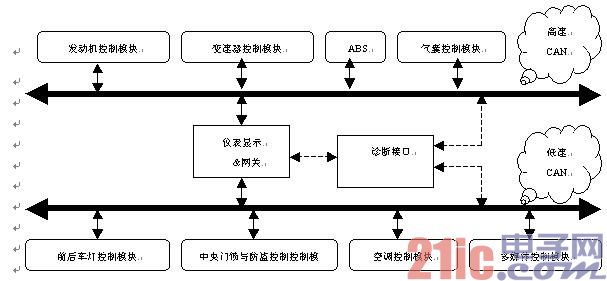
CAN application in body control
In a typical SPC, the on-chip voltage regulator is typically a low-dropout (LDO) linear regulator, as shown in Figure 1. For this reason, the main challenge for designers is thermal management because LDO power dissipation is relatively high. For a regulated current supply current of 150 mA at 5 V, the SBC should be able to dissipate up to 1.3 W of total power. If the SBC's LDO contains a built-in bypass component, this power is dissipated inside the SBC package. SBCs for modules that require more current (typically above 250 mA) are typically designed for use with external bypass components. This effectively dissipates the power dissipation between the SBC and the external MOSFET, thereby extending the practical ambient temperature range.
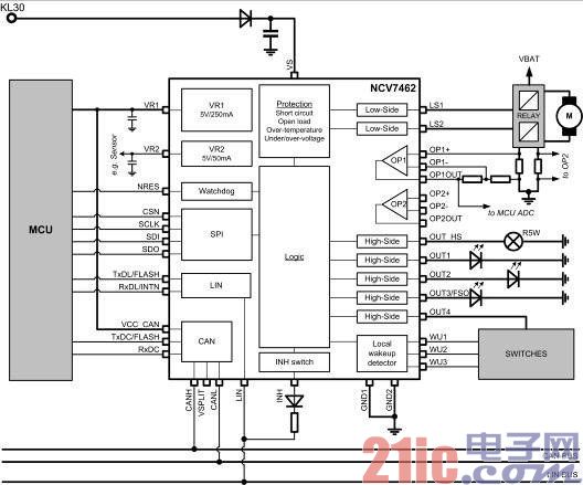
figure 1
Improving the power efficiency of the power supply circuit, such as using a switch mode DC-DC converter at some or all of the LDOs, can significantly reduce the power loss per SCAN of each CAN node in the car. This can help simplify heat management and improve fuel economy.
With carefully chosen converter architectures, SBCs with switch-mode DC-DC conversion offer significant advantages for newer vehicles that use automatic stop-start (or micro-hybrid) technology. The automatic stop-start technology shuts down the engine when the car is stopped (such as waiting for a traffic light), which can reduce the fuel consumption in the city by about 15% to 20%; when the driver steps on the accelerator pedal (throttle), the engine automatically restarts. Make the system work effectively, and this process is transparent to the driver. To ensure that all systems on the CAN bus continue to function properly, the application must remain fully operational, even when the battery voltage drops to as low as 2.5 V during engine start-up. In this case, the step-up DC-DC topology allows the SBC to provide the required regulated output voltage under all operating conditions.
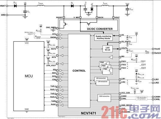
Figure 2: SBC with DC-DC converter
Local network
Today's cars may contain a large number of ECUs, and the number of ECUs in high-end models may be as high as 100 or so. Most ECUs, if not all, are connected to the CAN bus, so the CAN bus is always enabled. Some ECUs must remain active even when the engine is turned off to maintain functions such as remote unlocking (RKE). The fact that so many ECUs are connected to the bus has a major impact on overall power consumption.
Partial Networking (PN) is a technique used to reduce energy consumption while enabling the ECU to respond to wake-up commands. The system only enables partial networks as needed at certain times, while other nodes remain in a low power state. There are several possible local network applications. The selective wake-up function is defined for the CAN standard ISO 11898-6 issued for road vehicles as a means of providing local networks with high-speed media access. When an ECU does not require work, it may disconnect from the CAN network as long as no specific instructions are transmitted to this particular node.
In order to cooperate with the local network function, each node requires a "selective wake-up function" built in the dedicated transceiver. This selective wake-up feature reduces the current consumption of the inactive ECU to within the 100 μA average standby current limit typically specified by the automotive manufacturer. Even with such a power saving effect, the number of connection to the bus ECU is so large that the total energy consumption of the bus has a large influence on the fuel consumption of the automobile. Another disadvantage of this approach is the increased system cost associated with the additional selective wake-up circuitry that must be included in each IC. In addition, all nodes in the network need software adaptation to match the application local network. This adds to the large system development load.
Introducing a CAN repeater
By dividing the logical bus into two physical parts, one of the complete parts can be powered off when not in use, which can obtain valuable power saving effects, as shown in Figure 2. This can be done by introducing a two-way repeater on a module connected to the CAN bus.

Figure 3. Adding a module with a CAN repeater enables the bus to be split into two parts
The conventional module includes a CAN transceiver connected to the bus that converts the physical CAN signal into a digital signal that is processed by the microprocessor module. Normally, all modules connected to the bus are of this type. Adding a module with a built-in CAN repeater creates a point at which the bus can be physically divided into two parts.
As shown in Figure 4, the CAN repeater is connected to the microcontroller in a similar manner to a standalone CAN transceiver. Inside this device, each signal on port A is transmitted to port B, and each signal on port B is transmitted to port A. The CAN bus signal is interpreted in the microcontroller. The repetition of the CAN bus data is done inside the repeater chip. When a Go-to-Sleep command is received, the connection between the ports is broken, effectively disconnecting the network portion of Port B. All nodes on the disconnected section can enter a very low power sleep mode.
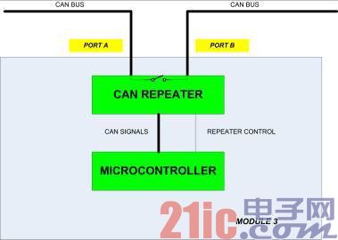
Figure 4. Internal architecture of the CAN Repeater module.
This method is simple and cost-effective because all nodes except one can be applied using standard ISO 11898-2 or ISO 11898-5 transceivers without software adaptation. Only one repeater is required. When using this technique, it is important to calculate the overall timing taking into account factors such as cable length, transmission speed, and additional delay caused by the repeater.
Splitting the bus in this way also enhances the vehicle's fault tolerance (such as cable to ground or battery short) capability. These so-called "hard" bus faults can be further limited by inserting additional bus repeaters if required. It also prevents "soft" errors with consequences such as increased electromagnetic radiation and heat dissipation from affecting the entire network.
in conclusion
Today's automakers are increasingly focusing on maximizing the energy efficiency of every system in a car to meet more stringent emissions and fuel economy goals. In order to meet the needs of car buyers and the earth, it is now more important than ever to make full use of new IC developments to manage electrical energy consumption more efficiently from various modes of use, from flameout to all system work.
The Hair Dryer is a combination of a set of electric heating wires and a small high-speed fan. When energized, the heating wire generates heat, and the wind blown by the fan passes through the heating wire to become hot air. If only a small fan rotates and the heating wire is not hot, then only the wind will blow out but not the heat.
Cordless Hair Dryer has the function of anti-leakage protection, safety, dexterity, lightness, low noise, etc. It can also solve the problem of dry burn and hot when blowing hair, so that you can avoid the trouble of cold and wet hair washing in autumn and winter.
The wind blown by the Portable Hair Dryer is dry. If it is used for too long, it will easily cause moisture loss and heat damage. The secret to minimize the damage is: pat the moisture on the hair first with a towel and gently hand Comb your hair and then use the hair dryer.

Hair Dryer
Cordless Hair Dryer,Hooded Hair Dryer,Travel Hair Dryer,Portable Hair Dryer
Taishan Jie Da Electrical Co., Ltd , https://www.ts-jieda.com