Digital tachometer based on magnetic sensor design
The digital tachometer is one of the necessary instruments in the mechanical industry to determine the speed, line speed or frequency of the motor. Most commonly used are handheld centrifugal digital tachometers. Speed ​​measurement is essential in all areas of the national economy.
The circuit of the digital rpm table is shown in the figure. It is mainly composed of a magnetic disk with permanent magnets, a Hall integrated sensor, a gate circuit, a time base signal circuit, a power supply count, and a digital display circuit. The counting and digital display circuit uses the CMOS-LED digital display component CLlO2, which can count and display digital.
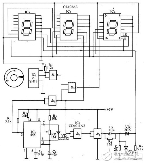
Figure 1 circuit diagram
The input shaft of the turntable is connected to the rotating shaft to be tested. When the measured shaft rotates, the turntable is rotated accordingly. When a small permanent magnet on the turntable passes through the Hall integrated sensor IC1, IC1 converts the magnetic signal into a rotational speed electrical signal. The signal is inverted by the NAND gate 1 to the input of the NAND gate 3, and the other NAND gate 3 is terminated with a square wave pulse signal from the time base circuit IC2. This time base signal is used to control the opening and closing of the NAND gate 3 to form a gate so as to control whether the speed signal can be output from the NAND gate 3.
When the power is turned on, the speed signal is immediately sent to the input terminal of the NAND gate 3. If the time base signal is low at this time, the gate is closed, and the speed signal element method passes through the gate. When the first time base signal arrives, the gate is opened, and at the same time, the LE terminals of the CMOS-LED digital display components IC4, IC5, and IC6 are in a registered state. The rising edge of the time base signal also triggers the inverter composed of NAND gates 4 and 5 and the differential reset circuit composed of R4, R5, R7, C3, VD2 and VD3. The reset pulse is output from VD3 and then applied to IC4. The R terminal of IC5 and IC6 resets the address device to zero. After completing the above functions, the time base signal remains high for one unit time (for example, lmin). During this time, the gate NAND gate 3 is always on, and the speed signal is sent to the LED digital display component through the strobe gate to achieve counting in unit time. At the end of the unit time, the time base signal returns to a low level. At this time, the gate is closed and the LE end of the automatic counting circuit is strobed. At this point, the counter's count content is sent to the register and its contents are displayed at the same time. When the second time base signal arrives, the contents of the counter are cleared again and the above process is repeated. However, the contents of the registers and displays at this time remain unchanged, and only after the second sampling is completed, will be updated to display new test results.
WS2811 digital led strip is single signal transmission Led, the same as WS2812B and SK6812 with three-channel circuit,
But It is difference,the WS2811 IC can be inside or outside. and the working Voltage is DC5-24V, can be program and apply to all kinds of electronic products, electrical equipment running horse lamp, led pixel screen etc.
It is the most common product and demand on the market.
Waterproof Strip,WS2811 RGB LED Strip,WS2811 LED Strip,WS2811 Digital LED Strip
SHEN ZHEN SEL LIGHTING CO.,LTD , https://www.sel-lighting.com