Transformer switching power supply biggest advantage is that the transformer can output multiple sets of different values ​​of voltage at the same time, change the output voltage and output current is easy, just change the transformer turns ratio and the size of the enameled wire cross-sectional area can be; In addition, the transformer early, The subordinates are isolated from one another and do not need to share the same ground. Therefore, the transformer switching power supply is also known as off-line switching power supply. The offline here does not require input power, but there is no wire connection between the input power supply and the output power supply, and the energy is transmitted exclusively through magnetic field coupling.
Transformer switching power supply Transformer isolation of the input and output of the greatest benefit is to improve the insulation strength of the device, reduce safety risks, while also reducing EMI interference, but also easy to carry out power matching.
Transformer switching power supply has single excitation transformer switching power supply and double excitation transformer switching power supply. Single excitation transformer switching power supply is commonly used in low power electronic equipment. Therefore, single excitation transformer switching power supply is widely used. The double-excited transformer switching power supply is generally used in relatively large-power electronic devices, and the circuit is generally complicated.
The disadvantage of the singly-transformed transformer switching power supply is that the volume of the transformer is larger than that of the spurious transformer of the double-excited transformer switching power supply, because the magnetic core of the transformer of the single-excited switching power supply only works at the single end of the magnetic circuit curve, and the magnetic circuit The area of ​​the curve change is small.
1-1. How a Single-Transformer Switching Power Supply Works
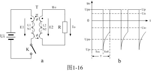
When the control switch K is turned on, the DC input voltage Ui first powers the primary winding N1 of the transformer T. The current will generate a self-induced electromotive force e1 at both ends of the primary winding of the transformer N1; at the same time, through the mutual inductance M, The induced electromotive force e2 is also generated at both ends of the transformer secondary winding N2; when the control switch K suddenly turns from the on state to the off state, the energy (magnetic energy) stored in the transformer primary winding N1 is also generated. Back-EMF e1; At the same time, through the action of mutual inductance M, an induced electromotive force e2 is also generated in the secondary winding N2 of the transformer.
Therefore, the direction of the electromotive force induced in the primary and secondary windings of the transformer is different before and after the control switch K is turned on.
The so-called single-extension transformer switching power supply refers to the switching power supply within a working period, the primary coil of the transformer is only excited by the direct voltage once. In general, a single-transformer switching power supply provides power (or voltage) output to the load in only one half cycle. When the primary coil of the transformer is just excited by the DC voltage, the secondary coil of the transformer also just provides power output to the load. This transformer switching power supply is called forward switching power supply; when the primary coil of the transformer is just excited by the DC voltage, The secondary winding of the transformer does not provide power output to the load, but only provides power output to the load after the excitation voltage of the primary winding of the transformer is turned off. This transformer switching power supply is called a flyback switching power supply.
The waveform of the output voltage of the single-extension transformer switching power supply, because the output voltage is the secondary output of the transformer, therefore, there is no direct current component in the output voltage uo. The area of ​​the positive half-wave of the output voltage is exactly equal to the area of ​​the negative half-wave, which is the characteristic of the output voltage waveform of the single-extension transformer switching power supply. In Figure 1-16-b, when only the positive half-wave voltage is output, it is a forward-type switching power supply; conversely, when only the negative half-wave voltage is output, it is a flyback-type switching power supply.
Incidentally, the positive and negative polarity of the output voltage waveform of the transformer in Figure 1-16-b can be changed by adjusting the direction (phase) of the coil winding of the transformer. Strictly speaking, only when the duty cycle of the control switch is equal to 0.5, the output voltage of the switching power supply can be referred to as the positive and negative half cycle voltages. However, since people have become accustomed to the terms of positive and negative half cycles, so long as there is positive , negative voltage output power supply, we still used to call them positive and negative half weeks. However, in order to distinguish it from the voltage waveform when the duty ratio is not equal to 0.5, we sometimes refer to the voltage waveform when the duty ratio is not equal to 0.5 as positive and negative half-waves. Therefore, some occasions do not affect the understanding of the positive and negative half-wave voltage, or when the duty cycle is uncertain, we also used to refer to the positive and negative half-waves as positive and negative half cycles.
During Ton, the control switch K is turned on, and the input power Ui starts to apply power to the primary winding of the transformer N1. The current passes through both ends of the primary winding of the transformer N1, and a magnetic field is generated in the core of the transformer through electromagnetic induction, and a magnetic force line is generated. At the same time, a self-induced electromotive force E1 is generated at both ends of the primary winding N1, and an induced electromotive force e2 is also generated at both ends of the secondary winding N2. The induced electromotive force e2 acts on both ends of the load R to generate a load current. Therefore, under the combined effect of primary and secondary currents, a magnetic field generated by the primary and secondary coil currents flowing through the transformer will be generated in the core of the transformer. The magnitude of this magnetic field can be used as magnetic flux (abbreviated as magnetic flux), ie, The number of magnetic lines is Ñ„.
Ñ„ = Ñ„ 1-Ñ„ 2 - K period (1-60)
The flux ф1 generated by the transformer primary coil current can also be divided into two parts. One part is used to cancel the flux ф2 generated by the transformer secondary coil current, denoted as ф10, and the other part is the magnetic flux generated by the excitation current, which is denoted as фΔ1. . Obviously ф10=-ф2, фΔ1=ф. That is, the magnetic flux generated in the core of the transformer depends only on the excitation current flowing through the primary winding of the transformer, and is independent of the current flowing through the secondary winding of the transformer; the magnetic flux generated by the current flowing through the secondary winding of the transformer is completely The flux generated by the current flowing in the other part of the transformer primary coil cancels out.
According to the law of electromagnetic induction, it is possible to list the equations for the primary winding of the transformer N1 winding:
E1=N1*dф/dt=Ui——K period (1-61)
Similarly, equations can be listed for the transformer secondary winding N2 winding loop:
E2=N2*dф/dt=Up——K period (1-62)
According to (1-61) and (1-62) can be obtained:
Up=e2=n*E1=n*Ui——K period (1-63)
In the above equation, Up is the amplitude of the secondary output voltage of the forward switching power transformer (positive phase in Figure 1-16-b); Ui is the input voltage of the primary winding N1 of the forward switching power transformer; n is the voltage Ratio, ie: the ratio of the output voltage of the secondary winding of the switching transformer to the input voltage of the primary winding, n can also be seen as the turns ratio of the secondary winding of the switching transformer N2 and the winding of the primary winding N1, ie: n=N2/N1.
It can be seen that during the period when the control switch K is turned on, the magnitude of the secondary output voltage of the forward switching power transformer is only related to the input voltage and the secondary/primary transformer ratio of the transformer.
Solar Flood Lights,Solar Flood Light With Camera,Solar Flood Light For Flagpole,Solar Flood Light Motion Detector Weatherproof
Jiangmen Biaosheng Solar Energy Technology Co., Ltd. , https://www.bsprosolar.com