Gravity remote control car based on Anxin No.1
I. Project design background and overview
With the continuous development of technology, wireless applications are becoming more and more widespread, and remote control toys and model aircraft are becoming more and more popular. The remote control for aircraft models is analog remote control, with flexible azimuth, speed and angle control, while general toys The remote control is a switch quantity, unlike the analog remote control, AD can be used to obtain a variety of states, while the remote control of the switch quantity has only two states of on and off. The general toy remote control, such as the remote control of the remote control car, controls its forward, backward and cornering actions by pressing the button, but this is too boring with the development of the society, and there is no mobile racing game.
The mobile racing game is based on the gravity sensing function of the mobile phone. Since it can be sensed by gravity, why can't we make a separate gravity sensing remote control? This design implements the design of this remote control through a mercury switch. Mercury switches have been used in gravity sensing applications, and there are fewer applications for remote-controlled vehicles. I will design a more complete gravity remote control car.
Second, the project design principle
1, an overview of the principle
This design is divided into two parts, the remote control part and the trolley part. The remote control AD ​​can control the speed of the car, and the tilt remote control can control the movement direction of the car. The remote real-time data will be displayed on the LCD 1602.
2, the hardware design principle
Remote control backplane: plugs in the LCD1604 and can pull out the control pin. It is plugged into the SLH core board through the DuPont line, and the bottom plate is also equipped with a 3-way mercury switch.
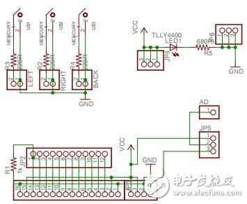
Figure 1 Remote control board schematic
5V to 3.3V control: Because the voltage range of NRF24L01 is about 2.7V~3.6V, and the power supply voltage of Anxin No.1 is greater than 3.6V, it must be connected through the switching circuit. as shown in picture 2.
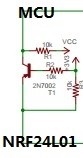
Figure 2 5V-3.3V transfer
Motor drive: As shown in Figure 3, when DIR=1, T3, T4 are on, T1, T2 are off. When PWM is low, T5, T6 are on, T7, T8 are off, motor is forward; when DIR= 0, T1, T2 are on, T3, T4 are off. When PWM is high, T7, T8 are on, T5, T6 are off, and the motor is reversed.
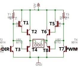
Figure 3 H bridge
3, software design principles
Remote control part: Through the AD conversion of Anxin No.1, an 8-digit precision value is obtained as the speed value of the trolley, and the speed of the trolley can be adjusted by adjusting the potentiometer. There are also 3 mercury switches. The mercury switch can be opened or closed by swinging the remote control to different orientations. The lateral direction of the remote control can be known by detecting the level of the connected pins. The measured speed value and direction are sent to the serial port assistant through the LCD display or through the serial port. Finally, Anxin No. 1 sends the speed value and direction to the car through the wireless module.
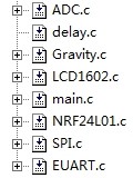
Figure 4 program module of the remote control part
Car part: The wireless module receives the speed value sent by the remote control and stores it in the Anxin No.1. The Anxin No. 1 matching speed value controls the two PWM outputs to control the car speed, and then matches the direction value to control the operation of the gear motor.
Figure 5 program module of the car part
4 Layer PCB
What is 4 layer PCB?
Four-layer circuit board is a kind of Printed Circuit Board. It is made of four layers of glass fibre, which can reduce the cost of PCB.
Compared with Double Sided PCB , multi-layer PCB have many advantages. They can be designed more compactly. They can greatly improve noise resistance and make layout easier.
There are also great differences between the 2-layer and 4-layer PCB. For details, please click: What's the difference between 2 layer and 4 layer PCBs?
4 layer PCB stackup and thickness


4 layer PCB stackup include two inner layers, inner layer 1 and 2, are sandwiched between the top and bottom layers. From top to bottom, the 4-layer PCB stackup like below ,The top, i.e. the signal layer (0.0014 in. width) is followed by a prepreg layer with a thickness of 0.0091 in. and dielectric constant of 4.2. The top layer is copper material. The prepreg layer is followed by inner layer 1 (0.0014 in.), referred to as the plane. A core sublayer is part of inner layer 1, which has a width of 0.037 in. This is followed by inner layer 2, which is another plane layer made with 1 oz. copper and is 0.0014 in. thick. Another prepreg sublayer constituting two sheets that are 0.0091 in. thick forms part of inner layer 2. The final layer, the bottom layer, is also 0.0014 in. thick, and is a signal layer as well. Interconnects are soldered and placed on the top and bottom layers.
4-layer PCB has two stacking forms
The standard 4-layer PCB stack is shown below, and GND and VCC can be switched according to the layer with more signals.

If you don't want to connect all the ground pins through the hole, there will be different stacks and wide power routing on the signal plane.

For the following reasons, this may be a better stack to use a four-layer PCB:
- The signal layer is adjacent to the plane. The signal running on the reference plane (whose voltage is exactly at the VCC) will still return on the reference plane.
- Signal layers are tightly coupled to their adjacent planes.
- The ground surface can be used as a shield for the internal signal layer. You will get better results, so that your plane height is as low as possible.
- Multiple grounding layers reduce the grounding (reference plane) impedance of PCB and common mode radiation.
When the high-speed signal changes the reference plane, there should be a nearby path for its return current to move between the two reference planes. Using two horizons, you can do this by connecting two planes directly to a single channel. For grounding and power layers, the connection must be made through capacitors, which usually require two through-holes and one capacitor. This means worse signal integrity and more circuit board occupancy. On the other hand, having a power plane can reduce the voltage drop on the power rail, thereby releasing the space on the signal layer.
PCB Board Thickness

4 LAYER 0.8 MM STANDARD BUILD

4 LAYER 1.6 MM STANDARD BUILD
0.4mm, 0.6mm, 0.8mm, 1.0mm, 1.2mm, 1.6mm, 2.0mm, 2.4mm, Please contact us if your board exceeds these.
4 layer PCB Prototype
4-layer circuit board prototyping refers to the trial production of Printed Circuit Boards before mass production. It is mainly used for electronic engineers to design circuits and complete PCB Layout, then to carry out small-scale trial production process to the factory, that is, proofing PCB. The production quantity of four-ply proofing generally has no specific boundaries. Generally, engineers call it proofing before product design has not been confirmed and test has been completed.
Notices for proofing of four-layer circuit boards
The precautions for the production of four-layer PCB samples generally include two groups, one is the Engineer group, the other is the PCB Sample manufacturer.
As a group of engineers, the matters needing attention in proofing are as follows:
1. Choose proofing quantity carefully to control cost effectively.
2. Specially confirm device packaging to avoid proofing failure due to packaging errors.
3. Conduct comprehensive electrical inspection to improve the electrical performance of PCB board.
4. Make good signal integrity layout, reduce noise and improve PCB stability.
As a manufacturer of four-layer circuit boards, the precautions are as follows:
1. Check PCB files carefully to avoid data problems.
2. Conduct process approval in an all-round way and process configuration with self-manufacturer.
3. Control production quantity, reduce cost and maintain quality.
4. Communicate with customers who need samples to prevent accidents in advance.
4 layer PCB price and cost
We specialize in Quick Turn PCB services with an industry leading turnaround time as fast as 24 hours. Three low-cost options for a small number of PCB prototyping needs. At the same time, we also provided Flexible PCB , Rigid- Flex PCB , Metal Core PCB , High-TG PCB, Aluminum PCB , PCB Stencils, PCB Assembly Services and so on. Using the same high-tech equipment as our full-service PCB, it can be manufactured quickly and with virtually no limits.
Cost of four layer PCB is higher than double sided PCB because of complexity of design and higher sensitivity. The better quality of signals, achieved by reducing distortion and propagation levels, is also a factor. Because of the higher levels of signal integrity and reduced interference levels, more manufacturers prefer four layer PCB.
4 layer PCB Manufacturing
We provide a full range of PCB functions to meet all your PCB needs. At present, we accept five PCB file formats (gerber file,.Pcb,.Pcbdoc.cam or.brd file format) for PCB manufacturing. But if you design a circuit board using Sprint-Layout software, you can send the. LAy6 file to us to manually generate the Gerber file.
JingHongyi PCB can provide you with multi-layer PCB board that meets RoHS standard. With laminated material, it can match high temperature in assembly process. It is important to remember that some lead-free assembly processes will require laminated substrates to withstand temperatures exceeding 260 degrees Celsius or 500 degrees Fahrenheit over a longer period of time. To solve this problem, we have high temperature laminates in stock, so that our customers can meet the higher temperature cycle requirements of some lead-free assembly applications.
Min. Order Quantity: 1 pcs
Material: FR-4
Finished Copper: 1oz/2oz/3oz(35μm/70μm/105μm)
Inner Layer Copper Thickness:1oz/1.5oz(35μm/50μm)
Silkscreen: White, Black, None
Surface Finishing: HASL with lead, HASL lead free, Immersion gold, Hard Gold ,OSP...
Shape: Custom Shape
100% Quality control
When making circuit boards, and after they are finished, we will test and inspect them strictly to ensure that the product reaches 100% eligibility rate. Preferential prices and higher quality have always been our constant pursuit:
- E-test
- AOI - Testing (Automatic Optical Detection)
- X-ray (check multi-layer registration accuracy)
- CCD-camera controlled drilling
- Impedance control


Videos for 4 layer PCB design and manufacturing
4 Layer PCB
Printed Circuit Board,4 Layer PCB,4 Layer PCB Board,4 Layer Printed Circuit Board
JingHongYi PCB (HK) Co., Limited , https://www.pcbjhy.com