Electronic Transformer Calibration System Based on LabVIEW
1 Introduction
With the acceleration of the construction of digital substations and smart grids, electronic transformers have developed rapidly.
Electronic transformers include electronic current transformers and electronic voltage transformers. In order to ensure the accuracy of the electronic transformer and ensure the safety and stability of the system, it is necessary to verify the transformer. The electronic transformer calibration system is used to verify the difference and angular difference of the electronic transformer.
Compared with traditional transformers, electronic transformers have undergone fundamental changes in the measurement principle, structure and output signal. The calibration principle and method are completely different from the traditional transformer calibration principles and methods, so the traditional transformers The verification method cannot be applied to the verification of the electronic transformer.
LabVIEW is a graphical programming language (G language). It is different from the traditional text-based programming language. It encapsulates various functions into function modules, which can quickly establish the system's graphical user interface. It has high development efficiency and development cycle. Short features are widely used in test and measurement and signal processing. The program written in the LabVIEW development environment is called the Virtual Instrument program (VI).
Based on NI PCI-4474 data acquisition board and LabVIEW development environment, this paper establishes an electronic transformer calibration system, which combines synchronous signal card and digital signal processing to verify the transformer. For the electronic voltage transformer with voltage level of 10~500kV and the electronic current transformer with rated current of 5~5000A, it can achieve the accuracy of five ten thousandths. It has the characteristics of high precision, stable and reliable performance, and meets the requirements of electronic type. Transformer ratio difference and angular difference check requirements. Field tests show the effectiveness of the calibration system established in this paper.
2. System composition
The verification system consists of two parts: hardware and software. The system hardware mainly includes the following parts:
(1) Standard voltage and current (electromagnetic) transformers (including booster and booster). The purpose of using standard transformers is to provide a standard output signal for the calibration system and must be traceable. The accuracy of the transformer is chosen to be 0.01, in order to improve the accuracy of the system measurement.
(2) PCI-4474 data acquisition board. The board is a dynamic signal acquisition card for high-precision dynamic and transient measurement. It has 4 synchronous sampling analog input channels with an input signal of -10~10VDC. In addition, it has 24-bit resolution and a maximum sampling rate of 102.4kS. /s.
(3) Sampling resistance. Select a sampling resistor with a resistance of 80Ω and a rated current of 0.05A with an accuracy of 100ppm.
(4) Voltage transformer 100V (100/√3V)/4V, accuracy 0.01; current transformer 5A/0.05A, accuracy 0.01.
(5) Synchronization card: used to synchronize the transformer unit of the tested transformer and the standard loop acquisition card.
(6) Merging unit: The main function of the merging unit is to synchronously receive the digital signal output by the 12-channel electronic transformer (12 channels are defined according to the DATASET data channel specified in the IEC60044-8 standard), and the frame format is specified according to the IEC60044-8 standard. And sent to relay protection, measurement and control equipment.
The merging unit generally provides a total of 12 current and voltage signals (all fiber transmissions), including 7 current signals and 5 voltage signals, which are packed according to certain rules and output through Ethernet. The merging unit is generally provided by the user and complies with the GBT-20840-7/8 and IEC61580-9 standards.
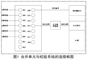
The connection between the merging unit and the verification system mainly includes two parts: one is a synchronous pulse signal connection, and the other is an Ethernet connection. The block diagram of the connection unit and the verification system is shown in Figure 1:
(7) Industrial computer. The industrial computer is connected to the standard A/D converter through a PCI-GPIB card with a communication protocol of IEEE488.2.
(8) Voltage regulator.
A Brushless dc electric motor ( BLDC motor or BL motor), also known as electronically commutated motor (ECM or EC motor) and synchronous DC motors, are synchronous motors powered by direct current (DC) electricity via an inverter or switching power supply which produces an alternating current (AC) electric current to drive each phase of the motor via a closed loop controller. The controller provides pulses of current to the motor windings that control the speed and torque of the motor.
The construction of a Brushless motor system is typically similar to a permanent magnet synchronous motor (PMSM), but can also be a switched reluctance motor, or an induction (asynchronous) motor.
The advantages of a Brushless Motor over brushed motors are high power-to-weight ratio, high speed, electronic control, and low maintenance. Brushless motors find applications in such places as computer peripherals (disk drives, printers), hand-held power tools, and vehicles ranging from model aircraft to automobiles.
12v brushless motor,12v brushless dc motor,12 volt brushless dc motor,12v dc brushless motor high torque,12v high rpm brushless motor,12v brushless dc motor 10000 rpm
Shenzhen Maintex Intelligent Control Co., Ltd. , https://www.maintexmotor.com