Three solutions for high-speed current sensing with wide dynamic range (3)
In many applications such as motor control, solenoid control, communication infrastructure, and power management, current sensing is a critical feature required for precision closed-loop control. How to design a wide dynamic range of high-side current-sense circuits is challenging for most engineers. Here are a few recommended circuits from ADI technologists Neil Zhao, Wenshuai Liao, and Henri Sino for your reference.
Three alternative solutions are presented in order of design complexity from high to low, which provide viable high-accuracy, high-resolution current sensing for a wide range of applications.
1. Construct a current sensor using discrete devices such as op amps, resistors, and Zener diodes. This solution is based on the AD8628 zero-drift amplifier.
2. Use high-voltage bidirectional shunt monitors such as the AD8210 to increase integration and use other external components to extend dynamic range and accuracy.
3. Use device-optimized devices such as the newly introduced AD8217. The AD8217 is an easy-to-use, highly integrated zero-drift current sensor with an input common-mode voltage range of 4.5 V to 80 V.
Solution 3: High-end current monitoring with zero-drift AD8217
Analog Devices recently introduced the AD8217 high-voltage current sensor with zero drift and 500 kHz bandwidth designed to enhance resolution and accuracy over a wide temperature, input common-mode and differential voltage range. Figure 3a shows a simplified block diagram of the device; Figure 3b shows a typical application.
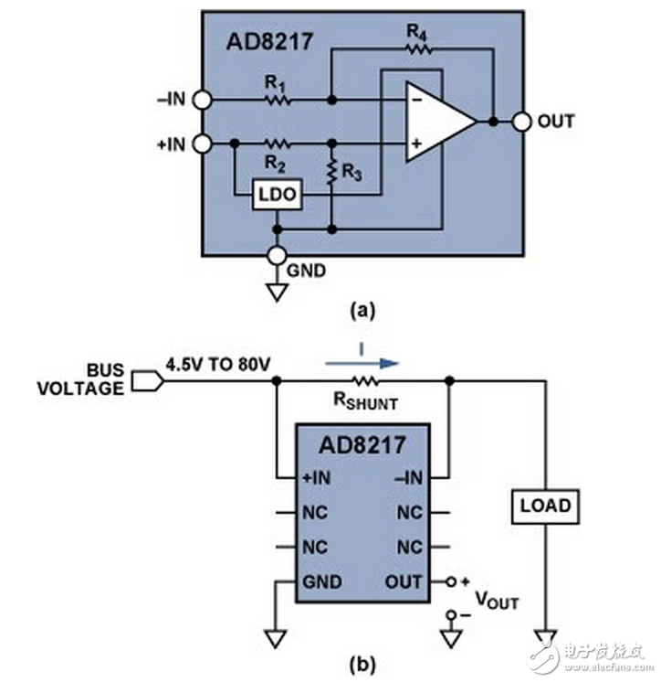
To measure the very small current flowing through the small shunt resistor, the AD8217 provides a minimum output range of 20 mV (over the entire temperature range), which is better than the 50 mV range of the AD8210. Therefore, if the minimum monitored load current on the shunt resistor produces a minimum output of 20 mV in the current sensor (equivalent to a minimum input of 1 mV), the user can choose to configure the AD8217 as shown in Figure 3b. The relationship between the output voltage of the AD8217 and the input current can be expressed by Equation 3:
The AD8217 contains a low dropout regulator (LDO) that provides a constant voltage supply to the amplifier. The LDO can withstand a high common-mode voltage of 4.5 V to 80 V, which is basically similar in function to the Zener diode in Figure 1.
The factory-set gain of the AD8217 is 20 V/V with a maximum gain error of ±0.35% over temperature. The initial offset rating is ±300 μV over the entire temperature range, and the temperature drift is very small, only ±100 nV/°C. These characteristics can improve any error budget. The buffered output voltage can be interfaced directly to any typical analog to digital converter. When the input differential voltage is at least 1 mV, the AD8217 provides the correct output voltage regardless of the common-mode voltage. When using a 10 mΩ shunt resistor as in the previous example, the minimum current can be as low as 100 mA.
The single-chip solution avoids the drift and power issues of discrete solutions.
Performance comparison
The test results obtained by comparing these three different methods are given in the following sections. The input current flowing through the shunt resistor is adjusted by changing the input voltage and load resistance during the test. In the data shown, an initial calibration has been performed to eliminate the initial gain and offset errors associated with all devices in the board.
Figure 4 is a linear plot of the output voltage on RL measured with the circuit shown in Figure 1 and the low end of the input current flowing through RSHUNT. RSHUNT is 10 mΩ; RG is 13 Ω; RBIAS is 100 Ω; R1 is 10 kΩ; load resistance is 200 Ω; RL is 200 Ω; Zener diode output is 5.1 V; op amp is AD8628; MOSFET is BSS84. The maximum relative error is 0.69%, and the average error after calibration is 0.21%.
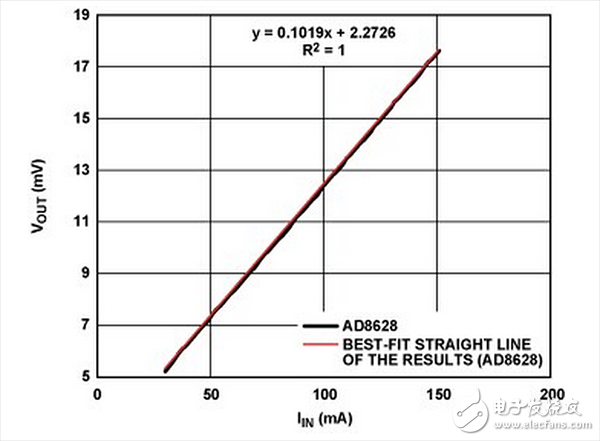
Figure 5 is a linear plot of the output voltage of the AD8210 measured with the circuit shown in Figure 2b versus the low end of the input current flowing through RSHUNT. RSHUNT is 10 mΩ; R1 is 20 kΩ; R2 is 0.5 kΩ; load resistance is 200 Ω; external reference buffer is AD8603. The maximum relative error is 0.03%, and the average error after calibration is 0.01%.
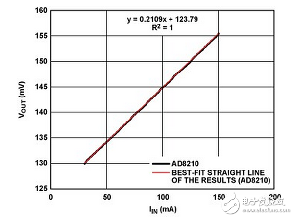
Figure 6 is a linear plot of the output voltage of the AD8217 measured with the circuit shown in Figure 3b versus the low end of the input current flowing through RSHUNT. The RSHUNT is 10 mΩ and the load resistance is 50 Ω. The maximum relative error is 0.088%, and the average error after linear correction is 0.025%.
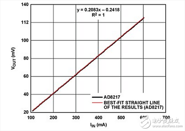
Note that it is necessary to focus on the low end of the range instead of covering the entire range from 50 mA to 20 A. The reason is that the linearity change is mainly in the range of the low output voltage (low unipolar current).
More stable performance
Disposable ecig have a completely enclosed design, reducing the need for charging and replacing cartridges. The no-charge design also reduces the occurrence of faults. It is understood that with rechargeable e-cigarettes, each cartridge needs to be charged at least once and the battery efficiency is extremely low, while the design of disposable ecig can solve this problem very well.Disposable ecig are very easy to carry on daily trips, no need for any operation in the use of airflow induction, direct suction can be out of smoke, meaning that you just need to suck directly on the hand can be the main feature of the small cigarette is practical portability is the main, its appearance is very small, no longer like the previous big smoke box mechanical rod nowhere to put.
The market outlook for disposable ecig
There has been a controversial topic regarding the use of disposable ecig. According to scientific studies, the long-term use of e-cigarettes can cause harm to the human body, no less than tobacco. Therefore, it is important not to overuse either type of e-cigarette - after all, smoking is bad for your health. Specifically, the PMTA requires that any new tobacco product be approved by the FDA for legal promotion and that the FDA consider all aspects of the product to be beneficial to public health. Our products can always be sold under the supervision of the PMTA at cost and are prohibited for sale to minors. We have strict guarantees regarding the quality of our products.
Disposable E-Cig,Disposable Vape Pen Oem,Best Disposable Vapes,One-Time Use Vape
Shenzhen MASON VAP Technology Co., Ltd. , https://www.cbdvapefactory.com