Adam Taylor plays the 57th of the MicroZed series: Zynq and PicoBlaze Part II
So far, we know how to instantiate a PicoBlaze soft core processor in a Zynq SoC-based system. In this blog, we will continue to explore more about how to generate PicoBlaze programs and how to use the JTAG interface to update programs instead of recompiling the entire design.
Obviously, the first step we have to do is to write the assembler to implement the functionality we require. We can use PicoBlaze or a more advanced IDE such as fidex() to write the program.
The suffix of this assembly file is .psm, and the PicoBlaze processor is compiled using the PicoBlaze assembler. For details on the PicoBlaze assembly syntax, see the UG129 and All_kcpsm6_syntax.psm files in the download package. This grammar is very simple and easy to understand.
The example of LED flashing we did last week used the following code. In this example, the PicoBlaze processor clocked at 40MHz, and the four flashing LEDs of the IO load board flashed at 2HZ. We use a counter that counts down to complete the blink rate. First, set a preset count value. When decrementing to 0, the LED state is inverted.
Since the PicoBlaze instruction takes two cycles to execute, we first calculate the preset value:
1. 5s / 50ns = 10,000,000 cycles
However, look at the code below where there are five instructions to execute in the loop delay, so we divide the value calculated above by 5, so we get a constant equal to 2,000,000 (hexadecimal 1E8480).
This is the LED flashing code that eventually runs on the PicoBlaze.
NAMEREG s0, led ;rename S0 register to led
As 8 bit processor we need four delay loops 256 * 256 * 256 * 256 = 4294967296
CONSTANT max1, 80 ;set delay
CONSTANT max2, 84 ;set delay
CONSTANT max3, 1e ;set delay
CONSTANT max4, 00 ;set delay
Main: LOAD led, 00; load the led output register with 00
Flash: XOR led, FF; xor the value in led register with FF ie toggle
OUTPUT led,01; output led register with port ID of 1
CALL delay_init; start delay
JUMP flash; loop back to beginning
Delay_init: LOAD s4, max4;
LOAD s3, max3;
LOAD s2, max2;
LOAD s1, max1;
Delay_loop: SUB s1, 1'd; subtract 1 decimal from s1
SUBCY s2, 0'd; carry subtracTIon
SUBCY s3, 0'd; carry subtracTIon
SUBCY s4, 0'd; carry subtracTIon
JUMP NZ, delay_loop;
RETURN
The next step is to compile the source code using the assembler in the download package to generate a storage file (we used the VHDL language for the FPGA we used last week), a log file, and a hex file (.hex).
After writing this program, we opened the last week's design and instantiated it. Although in the joint test, if we need to change the content of the program, one of the methods is to use the JTAG downloader to burn. The JTAG downloader allows us to modify the RAM content of the PicoBlaze processor via the JTAG interface. Then we can test this updated program to use this updated program before we recompile the FPGA configuration so that it can run automatically in RAM.
We can only use one PicoBlaze with this JTAG downloader. If a design has several PicoBlazes (theoretically feasible), we need to make sure that only one processor uses the JTAG downloader. We do this by setting Generic as follows when instantiating PicoBlze:
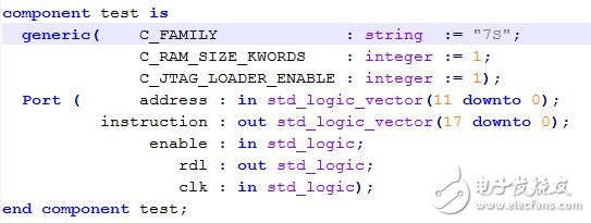
After setting up the JTAG downloader, it only corresponds to one of our PicoBlaze, we then use the JTAG downloader to burn our compiled hex file.
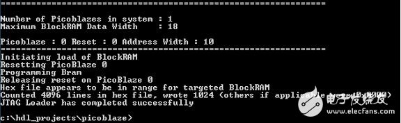
The process is very simple. First select the correct version from your downloaded JTAG_loader folder and copy it to your working folder (where your hex is), depending on the operating system you are using. After completing this step, you can open a command window and navigate to your working directory, and use the following command:
Jtagloader –l .hex
Note that I have renamed the version of jtagloader.exe for my operating system.
With the download, you will see that the JTAG downloader pauses the work of this processor and downloads the new program to memory before resetting the processor, and then your new program restarts.
Although this is a very powerful tool, it allows you to download and verify program modifications, but unfortunately. It does have a few flaws. such as,
The next time you power up the board, the original program is executed instead of the updated one. At the same time, you can only update an instantiated PicoBlaze before generating a new FPGA configuration bitstream.
Thanks a lot to this Zynq architecture for letting us overcome these limitations and in the next few blogs we will see how to do this, which will be very exciting!
Shenzhen Chaoran Technology Corp. , https://www.chaoran-remote.com