Design scheme of robot motion control system based on ADT850
The hardware and software structure of a mobile robot's motion control system is mainly introduced. The control system is composed of industrial PC, ADT850 motion control card and related sensors; the operating system adopts Windows98 system, developed by Visual C++6.0, and uses modular and multi-tasking mechanism of Windows thread to realize control program design; according to state feedback control Theory, designed a mobile robot path tracking control algorithm. The experiment demonstrates the effectiveness of this control system and control algorithm.
introduction
The mobile robot is an intelligent robot capable of autonomous movement in an unknown environment. It integrates multiple functions such as environment perception, dynamic decision-making and planning, and motion control. The main function of the motion control system is to track the upper-level planning path [1]. .
With the development of science and technology, the field of human research activities has expanded from land to seabed and space. The use of mobile robots for space exploration and development has become one of the main means of developing space resources in the world's major technological developed countries in the 21st century. Research and development of lunar exploration mobile robot technology will greatly promote the research of related cutting-edge technologies including mobile robot motion control [2].
In this paper, a mobile robot motion control system based on industrial computer (IPC) and ADT850 motion control card is proposed to realize the motion control of the vehicle body and sensor head of the mobile robot. The modular and multi-threaded software design method of Windows system makes the system have better openness and easy function expansion. Aiming at the system, a path tracking control algorithm for mobile robot based on state feedback is proposed to achieve stable and effective stabilization control.
1 hardware structure of motion control system
1.1 Description of the problem
Accurate self-positioning is a basic requirement for mobile robot motion control systems. Self-positioning is to obtain the position and orientation angle of the robot itself relative to a fixed coordinate system (collectively, the pose). Therefore, from the perspective of system hardware level, mobile robots must have certain sensors to obtain these pose information, such as using the photoelectric encoder fixed on the drive axle to calculate the position of the robot by measuring the motion increment of each motor. The fiber optic gyroscope is used to measure the direction angle of the robot in the horizontal plane, and the inclination sensor is used to measure the inclination angle of the robot and the horizontal plane. In addition, the mobile robot motion system also needs to receive the upper decision system path planning information and feedback the robot state information to the decision system, so the system needs to have better communication capabilities.
1.2 hardware system structure
The motion control system consists of computer system, sensor system, drive control system and power system (Figure 1). Among them, the computer system uses a general industrial computer (IPC), which ensures better scalability of the entire system. The sensor system includes an encoder, a fiber optic gyroscope, and a tilt sensor. The encoder is used to measure the actual amount of rotation of the wheel; the fiber optic gyroscope is used to measure the directional angle of the robot body in the horizontal plane; the tilt sensor is used to measure the inclination of the robot body and the horizontal plane. The drive control system includes the ADT850 motion control card and stepper motor driver. The power system uses two sets of Ni-MH 12Ah battery packs to independently supply power to the computer system and the drive system. The computer system uses a 24V DC source, and the stepper motor uses a 36V DC source, which can support the system to work continuously for 2~3 hours.
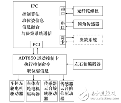
Figure 1 Mobile robot motion control system hardware structure block diagram
The fiber optic gyroscope and the tilt sensor transmit the attitude information of the mobile robot to the IPC through the serial port, and the position information of the mobile robot collected by the encoder is transmitted to the IPC through the I/O of the ADT850 motion control card. After obtaining the pose information of the mobile robot, IPC performs corresponding fusion processing, and then executes the corresponding control algorithm according to the path planning information provided by the upper decision system, and sends a control command to the motion control card. The control command is converted to a pulse signal that controls the stepper motor through the motion control card.
The ADT850 motion control card is a high-performance four-channel servo/stepping control card based on the PCI bus. In this system, two channels are used for the drive control of the left and right wheels of the robot body, and the other two channels are used for the sensor. Rotation and pitch motion control of the gimbal. The pulse output mode can be a single pulse (pulse + direction) or double pulse (pulse + pulse) mode, here the former method, the maximum pulse frequency is 4MHz. Position management uses two up/down counters, one for the internal management of the drive pulse output logic position counter, and one for the encoder input signal as the actual position counter with up to 32 bits of counter. There are also external input signal interfaces such as in-position signals, alarm signals, and servo-on signals. Provide a variety of motion control methods, such as quantitative exercise, continuous motion, zero return exercise. Speed ​​control can be used for constant speed and linear or S-curve acceleration and deceleration. It can be used for asymmetric linear acceleration and deceleration. It can be decelerated automatically or manually. There are two 32-bit compare registers per axis for generating interrupts or as software limits. And each axis has 8 input signal terminals, including 2 positive and negative limit signals, 3 stop signals, 1 servo alarm signal and 1 universal input signal. Except for the limit signal, the remaining signals can be set as invalid as a general-purpose input signal. All digital input signals have an integral filter with 8 filter time constants to prevent interference. The maximum output speed of each axis can be determined by setting the override parameter. The setting range of the drive speed, acceleration/deceleration and other parameters is only between 1 and 8000. If you need to set a value of 8000 or higher, you must increase the value. Magnification, but after increasing the magnification, the resolution of the speed will be reduced accordingly. Therefore, the minimum magnification is set under the condition that the highest driving speed can be achieved. Since the maximum speed of the mobile robot is 0.8m/s and the pulse frequency is 64kp/s, the minimum magnification should be set to 8.
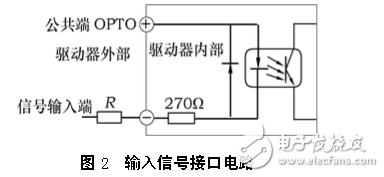
There are three input signals for the stepper motor driver. They are: step pulse signal CP, direction level signal DIR, and offline signal FREE. They are connected to the negative input of the optocoupler through a 270???? current limiting resistor inside the driver, and the circuit form is exactly the same, see Figure 2. The OPTO end is the common positive end of the 3-way signal (the positive input end of the 3-way optocoupler), and the three input signals are connected to the common internal mode in the driver, so the OPTO end must be connected to the VCC of the external system, if the VCC is +5V It can be directly connected; if VCC is 12V, external current limiting resistor R=680???? must be added externally. If VCC is 24V, external current limiting resistor R=1.8k???? must be added to ensure the internal of the driver. The optocoupler provides 8~15mA drive current. The stepping pulse signal CP is used to control the position and speed of the stepping motor. That is to say, the driver drives the stepping motor to rotate a step angle every time a CP pulse is received, and the frequency of the CP pulse changes while the stepping motor rotates. Changing and controlling the number of CP pulses allows the stepper motor to be accurately positioned. This makes it easy to achieve the purpose of stepping motor speed regulation and positioning. The direction level signal DIR is used to control the direction of rotation of the stepper motor. When this terminal is high, the motor is a steering; when this terminal is low, the motor is another steering. Motor commutation must be performed after the motor has stopped, and the commutation signal must be sent after the end of the last CP pulse in the previous direction and before the first CP pulse in the next direction.
1.3 software system structure
The operating system of the control system adopts Windows98, the program development system adopts Visual C++, and the programming method such as modularization and multi-tasking mechanism of Windows thread is adopted, which not only facilitates program debugging and modification, but also realizes quasi-parallel distribution of control system. Processing [3].
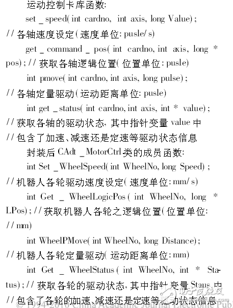
First, using the development library function provided by the ADT850 motion control card, it encapsulates the operation of each channel of the motion control card into an operation function for each wheel of the robot. These functions belong to the member function defined as the CAdtMotorCtrl class. Examples are as follows:
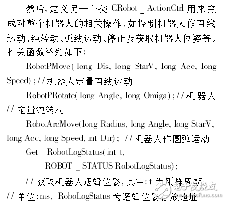
Through the above two classes, the hardware control and hardware parameters of the motion control card and the robot body are basically shielded, so that the upper layer development is simpler and more convenient, and the development of the robot motion control program can be completed without knowing the hardware knowledge associated with it. . Make the system with good scalability. Its overall structure is shown in Figure 3:
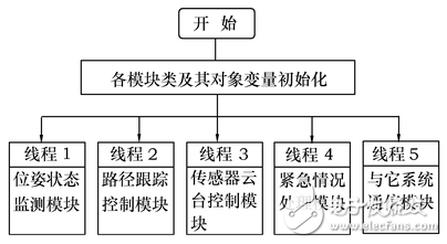
Figure 3 mobile robot motion control system block diagram
The pose state monitoring module is used to collect the input signals of each sensor, complete the monitoring of the position and attitude of the mobile robot, and use these signals as feedback signals of the control system; the path tracking control module implements the path tracking control algorithm of the mobile machine to the drive system Provide control signals; sensor pan/tilt control module controls sensor pan/tilt at angular velocity 8 (!)/s horizontal rotation and 4 (!)/s pitch motion; emergency processing module is used for various emergency situations; communication module completes motion control Communication between the system and the upper decision system.
In order to ensure the real-time performance of the control system, the timing control API function located at the bottom of Win????dows is used to obtain higher-precision timing signals, and the thread-priority scheduling can solve the system resources of each thread. Competing for problems, scheduling important and urgent tasks in high-priority threads; in addition, the ADT850 motion control card can independently respond to and handle some hardware interrupt events, which can be used to handle emergencies, such as robots requiring emergency stop, etc. , thereby further improving the real-time nature of the control system. Through experiments, this program can fully meet the real-time requirements of this mobile robot.
2 motion control algorithm
The most important part of the motion control of mobile robots is path tracking control. The task is to control the robot to make its motion trajectory asymptotically converge to the desired trajectory. Due to the non-linear body of the mobile robot body, the sliding and non-complete constraints of the tire and the ground, it is impossible to establish an accurate mathematical model [4]. Therefore, this paper proposes a path tracking control algorithm based on state feedback.
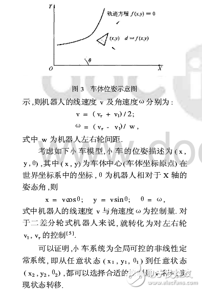
First, the kinematics analysis is performed on the two differential wheeled mobile robots. Let vl and vr be the left and right wheel speeds of the robot, as shown in the figure.
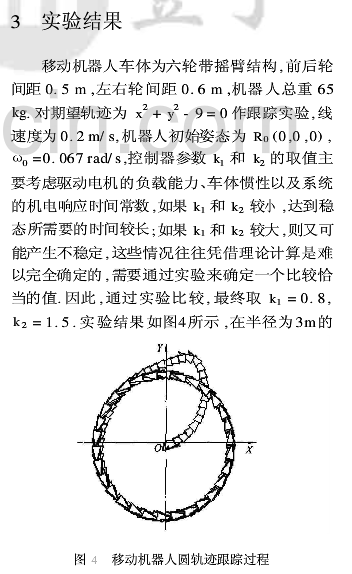
During the tracking of a circular trajectory with a radius of 3 m, the maximum overshoot is about 1.2 m, and it stabilizes on the desired trajectory after about 50 s, and the final steady-state error is about 0.15 m.
4 Conclusion
This paper introduces a mobile robot motion control system based on IPC and ADT850, including the hardware and software architecture of the system. The trajectory tracking control of the mobile robot is carried out by using the state feedback based control algorithm. The experiment proves the effectiveness of the control system and the control algorithm. The system adopts the modularization of Windows system and the multi-tasking mechanism programming method of Windows thread, which makes the control system have better expansibility and openness, and creates better conditions for further research and practicalization.
We cover many types of Connectors for industrial, electrical and automotive, such as IP68 and waterproof connectors, OBD diagnostic connectors, also the standard or custom-designed power connectors for MINI FIT, MICRO FIT, MATE-N-LOCK.
Connectors System,Board System Connector,Efi System Injector Connector,Efi System Car Connector
ETOP WIREHARNESS LIMITED , http://www.oemmoldedcables.com