Design of LPC23xx Adaptive Ethernet Communication Interface
Design of LPC23xx Adaptive Ethernet Communication Interface
The Ethernet interface is the hardware basis of the embedded system for Ethernet communication. With the advancement of microelectronics technology, many embedded control chips integrate Ethernet controllers, which makes the development of Ethernet interfaces in embedded systems more convenient [1]. LPC23xx is a microcontroller based on ARM7TDMIS core launched by NXP Semiconductors (founded by Philips) around December 2006. Compared with LPC21xx and LPC22xx, the most prominent feature is the integrated 10 Mbps / 100 Mbps Ethernet control on chip Device.
1 Structure and configuration of LPC23xx Ethernet controller
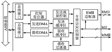
As shown in Figure 1, the functions of the main part of the LPC23xx Ethernet interface are as follows [2]:

Figure 1 Block diagram of the LPC23xx Ethernet interface
â‘ Control register, used to configure the working mode of the Ethernet controller, read the current status of the controller, etc .;
â‘¡ Bus interface, the interface for data exchange between AHB bus and Ethernet controller;
â‘¢ Receive / send DMA to realize batch data transmission from receive / send buffer to bus interface;
â‘£ Receive / send buffer, work in conjunction with DMA, temporarily store received / sent data;
⑤ Send flow control, insert Ethernet pause frame when the network load is too heavy to control the network flow;
â‘¥ Receive filter, filter out the control part of the Ethernet frame, and extract valid data;
⑦ MII (Media Independent Interface) / RMII (Reduced Media Independent Interface), an interface for real-time data communication with external PHY devices in accordance with the prescribed timing;
⑧ MMII (MII management interface), configure the working mode of the PHY device, and read the current status information of the PHY device.
Before using the LPC23xx Ethernet controller, the user must write the correct configuration information to the control register in Figure 1. The steps are as follows:
â‘ Clear the software reset status of LPC23xx Ethernet controller;
â‘¡ Configure the PHY device correctly through MMII;
â‘¢ Select the communication interface (RMII or MII) with the PHY device, limited by the chip size, NPC has launched LPC 2364, LPC 2366, LPC2368 and LPC2378 only RMII pins;
â‘£ Configure the first address and length of DMA engine and transceiver buffer;
⑤ Configure the MAC (Media Access Control) address of the Ethernet interface and select the Ethernet rate (10 Mbps or 100 Mbps);
â‘¥ Enable the receive / send channel.
In the above 6 steps, the key is the configuration of the receive / send buffer (step â‘£), the following is the detailed configuration process. In order not to affect the real-time nature of the data transmission of the Ethernet interface, the 16 KB RAM dedicated to the LPC23xx Ethernet controller is generally selected as the physical carrier of the transmit / receive buffer. According to the structure of the Ethernet frame, the receiving / transmitting buffers can be divided into several relatively independent buffer units (or no division), and each unit corresponds to one or more descriptors and status symbols. The descriptor is used to set the first address and control information of the corresponding part, and the status symbol stores the latest state information of the corresponding unit. These descriptors and status symbols form a ring array logically: the first address of the descriptor ring array is specified by RxDescriptor (receive descriptor base address register) / TxDescrip tor (transmit descriptor base address register), and the size is determined by RxDecriptorNumber (receive The number of descriptor registers) / TxDescriptorNumber (number of send descriptor registers) is specified; the first address of the array of status symbols is specified by RxStatus (receive status base address register) / TxStatus (transmit status base address register), the size is the same as the descriptor array. After the descriptor array and the status symbol array are formed, you can use RxProducerIndex (receive generation index register) / TxProducerIndex (send generation index register), RxConsumerIndex (receive consumption index register) / TxConsumerIndex (send consumption index register) Perform operations to realize data transmission / reception.
2 Control of network data reception and transmission
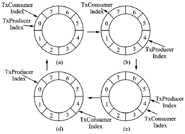
The NXP company has a more detailed introduction to the reception and transmission of data in its Ethernet controller in the LPC23xx user guide (reference [2]); however, there is no concept of a ring array of descriptors and status symbols. The control process is relatively mechanical, and this article has made improvements on the basis of practical engineering applications. Taking sending as an example, FIG. 2 is a continuous sending process, and the sending buffer is divided into 4 units, and 0 and 4, 1 and 5, 2 and 6, 3 and 7 are descriptors corresponding to these 4 units. The sending process is as follows:
â‘ If the last data transmission is completed, you will get the status shown in Figure 2 (a), at this time TxProducerIndex = TxConsumerIndex
â‘¡ Write the data to be sent into 4 buffer units, update TxProduceIndex to 4TxProducerIndex, which is the state shown in Figure 2 (b), and then the data starts to be sent;
â‘¢ Wait for the end of the last transmission (waiting can be achieved by interruption or inquiry), and the status of data transmission completed in Figure 2 (c) is obtained;
â‘£ If there is follow-up data to be sent, then write the data into 4 buffer units, update TxProducerIndex to 4TxProducerIndex, and then get the state shown in Figure 2 (d), after which the data will start to be sent
⑤ Repeat the above process to obtain the continuous sending process shown in Figure 2.

Figure 2 LPC23xx Ethernet controller continuous transmission process
The process of receiving and sending is similar. If the receiving channel of the LPC23xx controller has been correctly configured, an interrupt will be generated when 4 buffer units (assuming that the receive buffer is also divided into 4 units) are full. Read these 4 buffer units in the interrupt service program, and then update the RxConsumerIndex to 4RxConsumerIndex to complete the receiving process. It should be pointed out that the receiving and sending channels of the LPC23xx Ethernet controller need to be “generated†and then “consumedâ€. For the receiving channel, the Ethernet controller is the "producer" and the host is the "consumer"; the sending channel is the opposite.
3 PHY device configuration
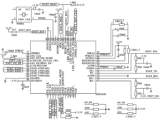
The LPC23xx controller provides RMII and MMII for data communication with PHY devices. Among them, RMII is responsible for sending and receiving network data, and MMII is responsible for the configuration of the PHY device and reading of the current state. This design selects the National Semiconductor Corporation DP83848I chip as the PHY device for the Ethernet interface, and its application circuit is shown in Figure 3. DP83848I can be configured by hardware or software. This design choice is configured by hardware, and the latest status of DP83848I is read by MMII.
The adaptability of the Ethernet interface is reflected by the DP83848I auto-negotiation function. The auto-negotiation function provides a mechanism for exchanging configuration information between the two ends of the network connection. Under this mechanism, the two ends will automatically select the optimal configuration [34].
DP83848I supports 4 different Ethernet working modes (10 Mbps half-duplex, 10 Mbps full-duplex, 100 Mbps half-duplex and 100 Mbps full-duplex), the auto-negotiation function automatically selects the highest performance based on the chip configuration Way of working. The levels of the AN_EN, AN1 and AN0 pins of DP83848I control the auto-negotiation function. During the low pulse (reset signal) input to the RESET_N pin, the levels of AN_EN, AN1 and AN0 will be sampled to determine the working mode of the chip. When AN_EN, AN1 and AN0 are all “1â€, they are connected in Figure 3 Into R1, R2 and R3, the four working methods are within the scope of negotiation [5].
The configuration process of DP83848I by LPC23xx is as follows:
①Send a reset signal with a pulse width greater than 1 μs, waiting for the completion of the auto-negotiation process;
â‘¡ Query the fifth bit of the basic mode status register (BMSR). When this bit goes high, it indicates that the auto-negotiation process is complete and the wait is over;
â‘¢ Query the 15, 14, 13, 12, and 11 bits of the BMSR to obtain the working mode of the Ethernet interface;
â‘£ Configure the working mode of LPC23xx Ethernet controller.

Figure 3 The hardware circuit of the PHY device of the Ethernet interface
For how to read and write the internal registers of DP83848I through MMII, please refer to page 149150 of reference [2], which will not be repeated here.
This article introduces an adaptive Ethernet interface based on the LPC23xx Ethernet controller and DP83848I as the PHY device. The application of newer electronic devices and electronic technology provides a reference for the design of the underlying hardware and software of the Ethernet in the embedded system, and also provides a hardware platform for the implementation of the TCP / IP protocol on the embedded system.
references
[1] Han Guangjie, Zhao Hai, etc. Embedded Internet technology and its review [J]. Small microcomputer system, 2004, 25 (5): 798-802.
[2] Philips Semiconductor. LPC2364 / 6/8/78 User manual, Rev 016, 200610.
[3] Wang Tingyao. Ethernet technology and application [M]. Beijing: People's Posts and Telecommunications Press, 2005.
[4] Liu Shubo, Ye Jiping. Design of Fast Ethernet Adapter in Embedded System [J]. Journal of Wuhan University: Engineering Edition, 2003, 36 (5): 123-126.
[5] NaTIonal Semiconductor. DP83848I PHY TER? Industrial Temperature Single Port 10/100 Mb / s Ethernet Physical Layer Transceiver, 200704.
Grille Led Panel Light is the new style among the panel lights. We are the manufacturer of producing energy saving interior lighting. This type of led grille light is in high quality and easy to install. There are three color temperatures with cool white, warm white and natural white of panel lights. It is used by non-isolated driver and built-in driver. The unique feature of the grille panel light is divided in double head and four head. These grille panels are mainly apply to home, office and school, etc.
Grille LED Panel Light
Four Headed Grille Light,Led Embedded Grille Panel Light,Square Grille Panel Light,Ceiling Grille Led Panel Light
Jiangmen Lika Lighting Electrical Appliances Co., Ltd , https://www.lika-led.com