Design of monitoring system for electric vehicle charging station based on MCGS
1 Introduction
Due to the fuel's reproducibility and cleanliness, electric vehicles have gradually become the target of the country's vigorous development in the new energy vehicle industry, and electric vehicle charging stations are the infrastructure that must be built after large-scale industrialization of electric vehicles. This article first introduces the structure design of the charging station monitoring system based on the special parking lot, designs the functions implemented by the monitoring system according to national standards, and finally introduces the realization of the charging station monitoring system based on the mcgs technology.
2 Structural design of charging station monitoring system
Referring to the State Grid Corporation's Guiding Opinions on Electric Vehicle Charging Facilities [7] [8], typical design of electric vehicle charging facilities [9], the technical realization route and development trend of electric power monitoring system, the charging station monitoring system adopts c / s and b / s Design in a combined manner, as shown in Figure 1
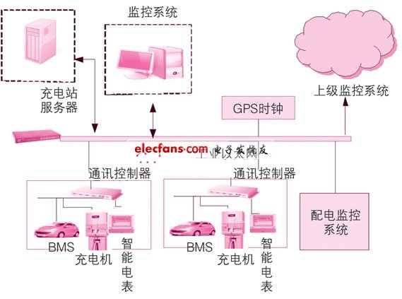
Figure 1 Structure diagram of charging station monitoring system
The entire monitoring system uses industrial Ethernet connection. The charger, bms (battery management system) and smart meters are connected to the Ethernet by the communication controller after protocol conversion and communicate with the host computer. System communication, these parts use c / s structure; the superior monitoring system communicates with the local monitoring system through Ethernet, and this part uses b / s structure; the server is responsible for storing various data information in the charging station, and the gps clock provides local clock calibration function. The monitoring system can realize the access of various types of chargers through industrial Ethernet, and monitor the chargers and the battery management system. In addition, the local monitoring system can communicate with multiple superior monitoring systems via Ethernet to achieve hierarchical and remote monitoring. This structure makes the system highly scalable and can meet the requirements of the continuous expansion of the scale of charging facilities.
Telephone Line Insulators are pin-type ceramic Telephone Insulators , Vintage Telephone Insulators mainly in three models, M-1, M-2 and M-3. Glaze is usually supplied with white glaze. Telephone Wire Insulators parameters are as follows:
| MAIN DIMENSIONS AND STANDARD PARTICULARS | ||||
| Type | RM-1 | RM-2 | RM-3 | |
| Main Dimensions | H | 140 | 100 | 80 |
| h | 49.5 | 32 | 30 | |
| D | 86 | 70 | 60 | |
| d | 51 | 44 | 35 | |
| d1 | 22.5 | 18.5 | 13 | |
| R1 | 12 | 8.5 | 7 | |
| R2 | 4 | 3.5 | 3 | |
| Insulation Resistance | 50000 | 40000 | 20000 | |
| Leakage Distance | 298 | 215 | 15 | |
| Net Weight, Each Approx., kg | 1.1 | 0.5 | 0.5 | |


We warmly welcome friends both domestic and abroad to visit our company, if you have any questions, please contact with us directly.
Telephone Insulators,Telephone Line Insulators,Telephone Wire Insulators,Vintage Telephone Insulators
FUZHOU SINGREE IMP.& EXP.CO.,LTD. , https://www.cninsulators.com