Three-phase half-controlled bridge rectifier trigger circuit diagram
A three-phase half-controlled bridge rectifier trigger circuit diagram shows how an older plastic extruder from the 1980s was powered. The system used a 380V three-phase power supply, which was stepped down by a transformer B (380V/190V, 32kVA) and then fed into a three-phase half-controlled bridge rectifier circuit to drive a DC motor D (Z2-72, 220V/22kW). The original trigger circuit consisted of 13 separate component boards, including integral circuits, speed adjustment, current regulation, trigger angle control, protection units, signal amplification, and more. This setup supported a double closed-loop DC speed control system with both current and speed feedback.
However, due to long-term disrepair, the triggering system became complex and unreliable. Components had aged significantly, leading to frequent failures and difficulty in maintenance. After analyzing the root cause, it was found that the main issue was related to the pulse triggering mechanism. To address this, the original complex trigger circuit was replaced with a modern three-phase full-control bridge rectifier trigger board (SMC-IIIE) developed by a university in Shandong.
This new control board is designed for a double closed-loop thyristor three-phase full-control bridge rectifier, featuring current and speed feedback. It can also be used for AC voltage regulators, soft starters, and DC speed controllers. The board offers a simple structure, easy installation, convenient debugging, high performance, low cost, and strong stability. It supports stepless adjustment of the output DC voltage for both full and half-controlled rectifier circuits.
The control board uses a single-board design with modular triggering and multi-layer microcomputer layout. It can trigger any single or two-way thyristor within a range of 5–1500A, with built-in overcurrent, current limiting, and overvoltage (overspeed) protection. Once triggered, the board blocks the trigger pulse and activates a normally open contact (GDL) of 380V/1A or 220V/3A to cut off the main circuit.
The input power for the board is dual AC 18V/0.5A, with GND connected to the center tap. The phase shift control voltage is 0–10V DC, with 15V, UG, and GND providing the reference voltage. A potentiometer with a resistance of more than 2.2kΩ and 1/2W rating is used, with one fixed terminal connected to GND and the other to 15V. TA, TB, and TC are connected to the three-phase synchronous transformer’s secondary windings, while the star point of the transformer is connected to the intermediate tap.
The trigger pulses are modulated at 20kHz. DL is the current feedback input, ranging from 0–10V, and SD is the speed feedback input, also 0–10V. During commissioning, the power supply must be adjusted to a positive phase sequence, ensuring the phase sequence of the synchronous transformer matches that of the thyristor power supply. The specific wiring is shown in Figure 1. The lower left part represents the original trigger system, while the upper left area within the dotted line shows the improved circuit.
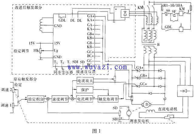
The improved trigger circuit is compact, easy to install, cost-effective, and provides stable and reliable control for the plastic extruder. It is also suitable for other similar systems using three-phase full or half-controlled bridge rectifiers with current and speed feedback. This upgrade significantly reduced the failure rate and maintenance complexity of the original system, delivering substantial economic benefits.
High Density Patch Panel,High Density Patch Panel,High Density Fiber Patch Panel,High Density Lc Patch Panel
Huizhou Fibercan Industrial Co.Ltd , https://www.fibercan-network.com