Causes and troubleshooting of overcurrent faults in the inverter control system - News - Global IC Trade Starts Here.
Overcurrent faults in frequency converters are among the most common and complex issues that operators may encounter. When such a fault occurs, the inverter’s protection system immediately activates, shutting down the unit and displaying a specific fault code or type. While many faults can be quickly diagnosed and resolved using the displayed error codes, others involve multiple factors such as overcurrent, short circuits, under-voltage, grounding, overheating, or harmonic interference. To effectively troubleshoot these issues, it is essential to follow a structured fault diagnosis process, often illustrated in a flowchart like the one shown in Figure 1.
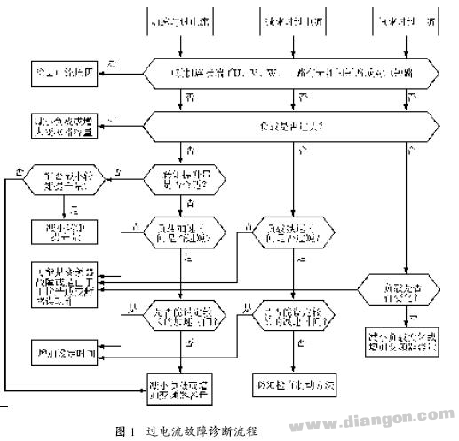
Modern inverters that use IPM (Intelligent Power Module) technology typically have built-in protection features including overcurrent, short circuit, undervoltage, grounding, and overheating. These signals are transmitted to the controller via the module's fault output terminal, Fn. Upon receiving this information, the controller halts the pulse output and displays the fault on the control panel. However, internal module faults can be challenging to trace. Therefore, when troubleshooting, it is crucial first to determine whether the trip was caused by external load issues or an internal inverter problem. Understanding whether the inverter tripped during acceleration, deceleration, or constant speed operation helps narrow down the possible causes and speeds up the diagnostic process.
General Troubleshooting Steps:
- If there are no visible signs of damage, disconnect the motor cables from the inverter and test the inverter and motor separately. Also, if an external control signal is connected, it should be disconnected for manual testing. If the inverter functions normally, it may not be damaged.
- Check if any settings have changed and reconfigure them if necessary.
- Use an external control signal or potentiometer to test the inverter’s response. If it works correctly, proceed to check the external signals and motor.
- External control signals usually come from sensors or controllers. These should be tested using appropriate methods, preferably with a field signal calibrator.
- For motor inspection, check its insulation using a multimeter or megohmmeter. If a contactor is installed on the inverter’s output side, verify that its contacts are functioning properly.
- If everything seems normal, consider running the motor using a commercial power supply for a period to observe any unusual behavior.
Analyzing Faults Using Operation Records:
If the inverter has a fault history, it might show that the current at the time of tripping exceeded the rated current or the electronic thermal relay setting. If the three-phase current is balanced, consider motor overload or sudden load changes, such as motor stalling or unexpected load disconnection. The former could be due to mechanical issues or bearing problems, while the latter may result from lost external control signals. Unbalanced current could indicate phase failure on the power supply side, motor terminal issues, or internal winding faults. If the current is within the rated range, the issue is likely internal, such as a faulty inverter module. Testing the resistance between the main output terminals (U, V, W) and DC bus (P, N) can help identify module damage. If the module is intact, the drive circuit may be at fault, though this is less common.Fault Analysis During Acceleration and Deceleration:
If the inverter trips due to overcurrent during deceleration, it may point to an issue with the upper half of the inverter bridge or its drive circuit. During acceleration, overcurrent in the lower half of the bridge or its drive circuit may be the cause. After confirming the bridge arm is damaged, replacing it should restore normal operation. If the inverter becomes hot after tripping, the carrier frequency might be set too high. Adjusting it to a lower level can prevent future issues.External Device-Related Faults:
Overcurrent faults can sometimes originate from external components. Common causes include:- Sudden motor load changes causing large inrush currents.
- Motor or Cable insulation breakdown leading to turn-to-turn or phase-to-ground short circuits.
- Loss or abnormality in the speed feedback signal from an encoder.
- Disconnection of control signal lines or sensor failures.
- Improper contactor operation due to oxidation or wear, causing phase loss.
Conclusion:
This article draws from real-world maintenance experience to analyze common causes of overcurrent faults in inverters. Since inverter faults can manifest in various ways, similar to other electrical equipment, they often involve unexpected situations. Addressing these issues requires both a deep understanding of the inverter’s working principles and the design of its protection circuits, as well as careful and thorough analysis to quickly resolve the problem and minimize downtime. Ensuring smooth production and operational efficiency depends on accurate and timely fault diagnosis and resolution.Aluminum-cased Electric Projection Screen
4-definition image quality, high-definition resolution of natural field of view, equipped with HDR high dynamic range image resolution, improving image contrast, wider open angle, consistent and clear visibility of images seen from different positions, as if you are in person.
Aluminum-Cased Electric Projection Screen,Hd Aluminum Shell Electric Projection Screen,Home Motorized Projector Screen,Motorized Electric Hd Projection Screen
Jiangsu D-Bees Smart Home Co., Ltd. , https://www.cI-hometheater.com