Design of Automobile TPMS System Based on RF Chip nRF905
The current TPMS (tire pressure monitoring system) is mainly divided into two types, one is indirect and the other is direct. The direct TPMS system has been affected by its poor accuracy of alarms and the interference of shielded electromagnetic waves and magnetic fields of the hub during wireless transmission.
This article refers to the address: http://
Based on the RF chip produced by Nordic, this paper introduces the circuit design and solution of the wireless transceiver system of the automotive TPMS system, and improves the above-mentioned direct TPMS system.
1 TPMS system design
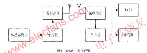
The TPMS system mentioned in this paper is completed by sending and receiving radio frequency information and prompting related information. In the tire part, there are mainly a pressure detecting module and a radio frequency transmitting module, and in the driver part, there are mainly a radio frequency receiving module and a display alarm module.
The pressure detection module mainly detects the pressure data of the measured tire in real time, and stores the corresponding changes of the data on the central processor, waiting for the radio frequency transmitting module to transmit. After receiving the data, the RF receiving module processes the data accordingly and displays the data on the accessory LCD, and judges the security of the data. After the tire pressure is found to exceed the acceptable range, the alarm is sent through the buzzer. Remind the driver. The specific working principle diagram is shown in Figure 1.
2 Comparison and selection of wireless transceiver chips
Due to the variety and number of wireless transceiver chips, the choice of wireless transceiver chips is crucial in the design. The correct choice can reduce the development difficulty, shorten the development cycle, reduce the cost, and bring the products to market faster. When selecting a wireless transceiver chip, you should consider several factors: power consumption, transmit power, receiving sensitivity, number of peripheral components required for transceiver chip, chip cost, and whether Manchester data encoding is required for data transmission.
Several important indicators used to evaluate wireless data transmission and reception are: receiving sensitivity, dynamic range, selectivity, receiving frequency stability, transmission ratio power, efficiency, transmission frequency range, power consumption and other factors. The following is a comparison of the performance of the three popular wireless transceiver chips at the current stage in the market, as listed in Table 1. 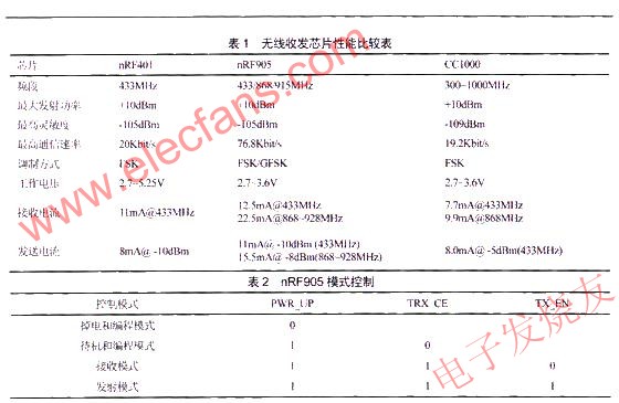
According to the expressions of Table 1 and the technical indicators, for receiving and transmitting data, the larger the range of the frequency band is satisfied, the higher the sensitivity, the smaller the receiving current under the same condition, the larger the emission current, and the fewer peripheral devices required. The transceiver chip application is more extensive and can be adapted to a variety of situations.
Based on the above considerations, the superiority of nRF905 is obvious, so choosing nRF905 in this design is the most suitable.
3 Introduction to nRF905
The wireless transceiver chip nRF905 is a monolithic wireless transceiver chip introduced by Nordic Corporation of Norway. The nRF905 is a single-chip RF transceiver operating in the 433/868/915 band. Because of the international ISM band, there is no so-called band limitation. The nRF905 consists of a fully integrated power management, frequency synthesizer, modulation receiver, power amplifier, crystal oscillator and regulator. The nRF905 features ShockBurst, which automatically processes the preamble and CRC checksum in the packet. The nRF905 configuration operation can be easily programmed via the SPI interface. The nRF905 consumes very little power. In the transmit mode, the output power consumption is only 11 mA at an output power of -10 dBm; the same power consumes 12.5 mA in the receive mode. And its POWERDOWN power-down mode can save more power.
3.1 nRF905 control mode
The nRF905 has two active modes and two power saving modes.
The activation modes include the ShockBurst RX receive mode and the ShockBurst TX transmit mode. Power-saving modes include PowerDown and SPI-programming power-down and SPI programming modes and Standby and SPI-programming standby and SPI programming modes.
The settings of TRX_CE, TX_EN and PWR determine the control of the mode. The specific control is listed in Table 2.
3.2 Connection between MCU and nRF905
The nRF905 communicates with the outside world via an SPI interface, and the rate is determined by the interface speed set by the microcontroller. In RX mode, the address match (AM) and data ready (DR) signals inform the MCU that a valid address and data packet have been received, and the microcontroller can read the received data via the SPI. In the TX mode, the wireless communication module automatically generates a preamble and a CRC check code, and the data ready signal informs the MCU that the data transmission has been completed.
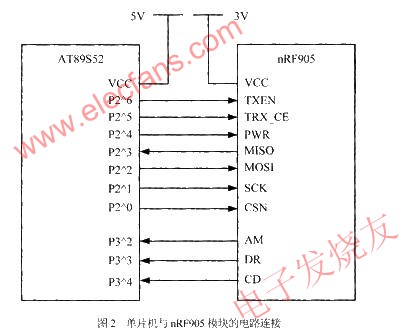
Here is the AT89S52 series MCU that is compatible with the 8051 produced by ATMEL. Because it communicates with the module, the control of the module is performed by the SPI interface bus of nRF905, because the AT89S52 does not have a dedicated SPI bus. Here, in order to communicate with the wireless module of the nRF905, the I/O port of the microcontroller is used for software programming to simulate the timing of the SPI to implement the SPI interface. Here, the (TXEN, TRX_CE, PWR) pins used for mode control and the (MISO, MOSI, SCK, CSN) pins controlled by the SPI interface are connected to the P2 port of the microcontroller, and the status outputs (AM, DR, CD). The pin is connected to 2 to 4 bits of the P3 port of the MCU. Figure 2 is a simple circuit connection between the MCU and the nRF905 module.
4 system software design
4.1 SPI interface check
Because the control of the nRF905 is performed by the built-in SPI bus, it is necessary to ensure that the operating system such as the microcontroller can communicate with the nRF905 through the analog SPI bus of the I/O port before the overall programming. Therefore, the system has designed a program part for verifying the SPI interface. Because the nRF905 module has a configuration register inside, it can write data and read data through SPI, and compare the results before and after the same to determine the correctness of the SPI operation.
If the array data obtained by the program operation is exactly the same as the written data, then the SPI interface of the nRF905 module performing this operation is all normal.
4.2 Program design of radio frequency communication
The key part of this system is the wireless radio communication part. When the pressure of the tire is collected, whether the data can be transmitted quickly is the premise and guarantee of whether the TPMS system can work normally.
The radio frequency communication is divided into a transmitting portion of the tire portion and a receiving portion of the cab.
When the nRF905 module performs the transmitting operation, its main control unit (the one-chip computer in this system) transmits the address and valid data of the receiving node to the nRF905 module through the SPI interface.
The send mode of the nRF905 module will be completed internally:
(1) The wireless system is automatically powered on;
(2) Packet completion (plus preamble and CRC check code):
(3) Packet transmission (100kbit/s, GFSK, Manchester coding).
In order to maintain the reliability of the system communication, the system uses the wireless data retransmission principle for the transmitting part of the nRF905, so the TRX_CE is set to always be high. The specific transmission flow chart is shown in Figure 3.

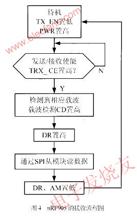
The main task of the receiving part in this system is to continuously detect the radio frequency electromagnetic waves in the air with the same radio frequency. When the electromagnetic wave is received, the corresponding CD, AM, and DR bits are set to 1 in sequence, and then the reading and writing program is started. .
After starting to detect the RF electromagnetic waves, it goes through three processes:
(1) The carrier detect CD is set high;
(2) Address matching AM is set high;
(3) Data ready DR is set high.
The high setting of DR means that the data has been received and saved to the internal registers of the nRF905 module. The next work is to read the data of the nRF905 module at a certain rate in the SPI interface operation mode, and then all the data will be After the reading and writing is completed, the AM and DR bits are reset to zero to ensure the normal reception of the next data. The specific receiving flow chart is shown in Figure 4.
5 Experiment and simulation
Here, the communication between the nRF905 and the MCU is carried out by means of bit-wise communication through the SPI interface. Therefore, the corresponding waveform test of the corresponding pin of the SPI should be presented as a square wave when receiving, and the tire is simulated by the computer. The pressure sensor transmits data to observe the waveform as shown in Figure 5.
It can be seen from the figure that the system is completely correct in the process of communication, and the intensity of the electromagnetic wave is very strong, and the communication purpose can be completely achieved.
In the design of the system, the radio frequency wireless communication method is used to establish the TPMS system, realizing the real-time detection of the pressure and temperature of the automobile tire. The system adopts the widely popular radio frequency communication technology and performs reliable data transmission in this environment, which is suitable for the short-distance communication development trend in the future. The overall reliability of the system is high, the stability is good, the cost is low, and it is convenient for transplantation, and it is convenient to add other functions. If you can get real applications, then the market prospects will be good.
· Backup Camera Blind Spot Camera When Parking Backing Reversing Your Trailer to Get Decent Image Quality to Make Your Reversing More Confident and Safety.
· Rear View Backup Camera and Monitor Kit : Waterproof Camera With Infrared Lights and HD Sensor & Night Vision.
· Reverse Backup Car Dash Security Sensor Camera For Trucks RV , Will Offer Much Safety Drive With It ,Extra Eyes on Trucks Behind and Side.
·
Quad Backup Camera Monitor System
Backup Camera Monitor,Quad Backup Camera Monitor System,Quad Split Monitor,Wired Quad View Monitor
Shenzhen Sunveytech Co.,LTD , http://www.sunveytech.com