Design and Implementation of Intelligent Automatic Irrigation System
O Introduction
Water is the foundation of life. The normal life activities of plants are based on the process of continuous water absorption, conduction and transportation, utilization and loss. In China, water resources are seriously inadequate, making China one of the 13 countries with the poorest freshwater resources in the world. Per capita possession of freshwater resources is only a quarter of the world's per capita possession. The lack of water resources has brought great obstacles and difficulties to China's agricultural development. The soil in which crops grow needs to maintain a certain degree of humidity. People usually irrigate crops according to the experience of planting. It is not possible to control the amount of watering in a timely or inaccurate manner, often causing flooding of large waters, which is largely wasted in vain. Part of the water resources. How to use limited water resources and take “water-saving agriculture†has become the growth point for agricultural production to obtain the best benefits and sustainable development. Therefore, the use of intelligent irrigation system for tap water power generation to control sprinkler irrigation and micro-irrigation systems can effectively reduce leakage and evaporation losses during field irrigation. The existing irrigation system requires an external power supply, which has certain safety hazards and is troublesome. The system can be used in areas without power supply, and its biggest advantages are water saving, energy saving and labor saving.
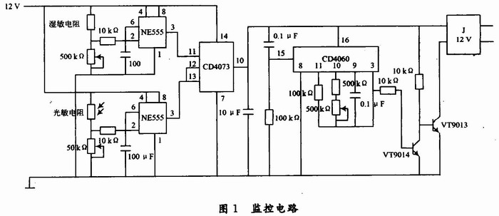
1 Design Objectives and Implementation Description The existing automatic irrigation system requires external power supply, which has certain safety hazards, and the existing automatic irrigation device program is generally solidified in the program memory of the system, and the irrigation time can be simply set. And the cycle time, can not be flexible according to the seasons, such as automatic adjustment and other shortcomings, the system connects the small DC generator to the fan blade to seal the special box, the water flow rotates the blade to generate electricity, and then stores the electric energy in the battery for monitoring Circuit and solenoid valves are powered. The device uses a humidity sensitive resistor and a photoresistor to detect signals, and tap water power is used as an automatic irrigation device that does not require an external power source. The device monitoring circuit is composed of a signal collecting part, an irrigation control part, a power supply part, and an execution part 4 part. As shown in Figure 1.
This article refers to the address: http://
1.1 Signal acquisition part
1.1.1 Soil moisture detection Silicon humidity sensor is used as a sensor to detect soil moisture. The response time is less than 5 s at 25 °C, and the soil moisture content is measured from 0 to 100%.
When the moisture sensitive sensor is inserted into the soil, the resistance of the humidity sensor is also different due to the difference in soil moisture content. The humidity is judged by the humidity sensitive resistor and IC1NE555. If the soil is dry, the humidity resistance is large, NE555 is turned over, and the output is high (approx. power supply voltage).
When adjusting, insert the humidity sensitive resistor into the water, adjust Rp1 to make the output of the NE555's 3 pin to 12 V, then take the humidity sensitive resistor out of the water and wipe it dry, adjust Rp1 to make 0 V output, so that it can be adjusted repeatedly several times. Claim.
1.1.2 Daylight intensity detection Through the photoresistor and NE555 to determine whether the light is strong, if it is strong at noon, IC2 NE555's 3 feet output low level, no water is watered regardless of whether the soil is dry or not. Here, NE555 is used to judge. When the daylight is weak, the resistance of the photoresistor is large, NE555 is turned over, and the output is high (for the power supply voltage).
1.2 Irrigation control
1.2.1 AND gate judgment When IC1 and IC2 simultaneously output a high level, IC3 CD4073 outputs a high level. IC3 outputs a low level regardless of any of IC1 and IC2.
1.2.2 Delay Circuit The oscillation time is realized by the CD4060 and the oscillating circuit composed of the capacitor resistor and the adjustable resistor. The time from the start of the CD4060 to the hold state is the irrigation time. The resistance of Rp3 can be adjusted to change the delay time.
1.3 Power supply part Because tap water flows faster in the water pipe, some of the kinetic energy can be recycled. The tap water is used to push the wind blade to drive the micro generator, store the electric energy generated by the generator into the lithium battery, and then transfer the electric energy in the lithium battery to the 6 V or 12V battery through the boost circuit. This part of the electrical energy is used to supply electrical energy to the automatic irrigation monitoring circuit.
1.4 The execution part uses the voltage output from the humidity detection section to control the pull-in of the relay, thereby controlling the on-off of the solenoid valve and implementing automatic irrigation.
A switch is added between the solenoid valve and the power supply to force it to open and close. When you want to enjoy the irrigated view, force the solenoid valve to open.
2 The conclusion test proves that the device has the following advantages:
(1) The system has good stability. The circuit is mainly composed of analog circuits, which requires low precision, good stability, and adjustable monitoring range and delay time.
(2) High security. The device is powered by tap water and has a low voltage output without any safety hazards.
(3) Low cost. The device does not need an external power supply, has no noise, low cost, small size, wide application range, and is easy to promote.
(4) Environmental protection. Tap water power saves energy, pollution, protection, and the environment.
(5) It can cooperate with garden developers, which can save a lot of manpower and material resources for the planting industry. This energy-saving equipment will become a benefit point for the planting industry.
(6) It can be used in remote mountain villages where electricity is not developed, so that local economic crops grow better.
Application:
The electric cable tray system are widely used for:
1.railway bridge cables laying
2.highway bridge cables laying
3.petrochemical engineering cables laying
4.post and telecommunication cables laying
5.computer cables laying
Ladder Type Corrosion Resistance Cable Tray
Cable Trunking System,Grp Ladder Outdoor Cable Tray,Powder Coating Ladder Cable Tray,Grp Corrosion Resistance Cable Tray
Jiangsu Loncin Electrical Equipment Co.,Ltd , http://www.loncincabletray.com