Design based on improving the far field illumination of LED array
Abstract: In this paper, the method of improving the illumination of LED array in the far-field target illumination surface is studied to meet the requirements of LED illumination system. With Lighttools software, the reflector model is first established on the LED array to observe the illumination intensity at the target illumination surface. And the relationship between the semi-intensity angle, and then by adding a lens in the reflector, appropriately changing the placement position, and establishing an illuminance grid on the target illumination surface, and finally further optimizing the shape of the reflector surface and the shape of the lens, High illumination in the area.
1 Introduction
Since the first LED in the 1960s, LED has been developed for more than 50 years. Although the luminous efficiency of LED is not high, its spectrum can be concentrated almost in the visible region, and the efficiency can reach 80% to 90%. The traditional incandescent light visible light conversion efficiency is only 10% to 20%. Because LED has small size, fast response, long life, energy saving, environmental protection and other advantages, it has been applied in many aspects, it will also be in the near future It will replace traditional light sources such as incandescent lamps. At the same time, large-scale semiconductor lighting applications will save energy to a large extent, and will also reduce carbon dioxide emissions and mercury pollution of fluorescent lamps. It is a green light source. Therefore, efforts are being made to develop semiconductor lighting. Industry has great significance for the sustainable development strategy of China's economy.
At present, the luminous flux of LED illumination source has a certain gap compared with common light sources such as fluorescent lamps. Therefore, in order to develop LEDs in the field of illumination, the key is to increase the luminous efficiency, luminous flux, etc. to the level of existing illumination sources. For this purpose, we must first improve the quality of the LED itself, to develop high-power and high-efficiency LED devices, and to optimize the design of LED lighting fixtures to improve their efficiency. Therefore, we study the secondary optical distribution design of LED light sources to meet the needs. Power LED lighting needs are extremely urgent. In this paper, a reflective reflector and an optical lens are added to the LED array to simulate the secondary optical design, which can improve the luminous efficiency of the device. Since in actual illumination, it is necessary to reach the illuminance at a certain distance. Requirements, such as lighting of buildings, lighting of streetscapes, etc. In response to this problem, this paper takes the topic of "LED lighting technology in the demonstration application of the Bund buildings" as a guide to study the design of LED far-field illumination.
2 Introduction of computer aided software
The software used in this thesis is Lighttools, which is a 3D solid modeling software developed by ORA. It can directly describe the light source in the optical system. Reflective cup and lens. The propagation of light in the optical system follows the law of reflection and the law of refraction of geometric optics. According to the different ways of light propagation in the optical system, computer-aided optical design software is usually divided into two categories, sequential ray tracing and non-sequential ray tracing. The former is mainly applied to imaging optical systems, while the latter is mainly applied to non-imaging optical systems. For example, illumination optics, projection optics, etc. Illumination optics is a non-imaging system that focuses on energy distribution rather than information transfer. It is divided into three parts, a light source, an optical system, and an illumination plane. The requirements for the illumination surface are mostly the requirements of illuminance. The illumination optical system belongs to non-sequence ray tracing. The non-sequence ray tracing analysis requires a large number of random rays of light intensity distributed by a certain source to trace in non-sequence ray. The order in which the light intersects the various interfaces in the system is uncertain.
The position of the light emitted by the LED light source at the time of exit. The direction is unknown. The position of the randomly outgoing light, the direction and the reflection and refraction. The absorption and absorption generated by each interface during travel and Monte Carlo (Monte) are required. Carlo) method to simulate. First establish a probabilistic model or stochastic process related to the solution, so that its parameters are equal to the solution of the problem sought, and then calculate the statistical characteristics of the parameters obtained by observation or sampling test of the model or process. Finally, the approximated values ​​are given. Therefore, both the primary and secondary optical design of the LED optical system need to trace a large amount of light to achieve the accuracy of optical system performance analysis.
3 LED array layout and introduction of secondary optical design
The illumination optical design is divided into one-time optical design and secondary optical design. The former is the internal design of the LED light-emitting tube. Once the LED is formed, the primary optical design is completed. The optical design determines the spatial light intensity distribution after the LED light is emitted. The secondary optical design of the LED is to increase the normal light intensity of the whole system by adding a reflector, a lens, etc. in the lamp with the LED, so that the limited light energy can be utilized more effectively and reasonably.
When selecting the LED light source, it is necessary to consider the size, arrangement, power, and illumination angle of the LED to achieve higher utilization of light energy. The single chip used in the project is the xM-L chip developed by CREE, and the chip size is 5mm. ×5mm, height is 3mm. Taking 150W floodlight as an example, according to the lighting demand and LED model, since the LED power is about 6.2w during normal operation, 24 chips are needed. In order to achieve a certain luminous flux and uniform illumination distribution Usually, multi-chip array is used as the surface light source. Increasing the arrangement of the LEDs is equivalent to increasing the effective area of ​​the light. The LED chip is composed of the light source module (as shown in Figure 1(a)). Considering the design requirements, the half-light intensity The angle is 15 degrees, that is, the light is emitted at a small angle, and the LED array is designed to be circular, arranged in a concentric circle. Considering the problem of the aluminum substrate routing, the first circle diameter is set to 18 mm, and the second circle diameter is 28.6 mm. The third circle has a diameter of 37.5mm, and the fourth circle has a diameter of 43mm. The four circles are all circumferential distributions of six single LEDs (as shown in Figure l(b)). By simulation, the light intensity distribution of the light source array is obtained. (As shown in Figure 1(c)), as can be seen from the figure,

Focusing on the two core problems of non-imaging optical systems, namely light intensity and illuminance, the research on LED illumination optical system is carried out. The optical simulation software is used to design the secondary optical of LED to improve the normal light intensity of LED.
4 optical design of the reflector
4.1 Determination of the geometry of the reflector
The single model xM-L chip guide software, without the reflector, establishes the receiving surface at 20m and 40m, and the obtained illuminance diagram is shown in Figure 2.
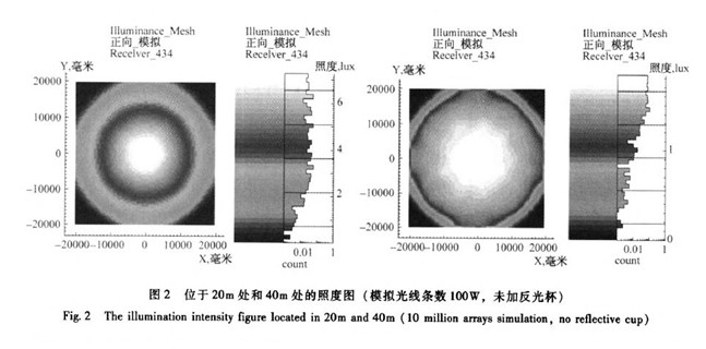
From the results, it can be found that to achieve a degree of illumination of the receiving surface of 40m at a distance of 40m, it is necessary to take certain measures. After comparing different forms of non-imaging optical components, the reflectors and lenses and LEDs are finally selected in combination with the actual situation. The system enables the projector to meet the specified exit angle requirements and achieve illumination requirements in the target illumination surface. The model used in the secondary optical design is micromachined, and its shape can control the divergence angle of the LED device. Directing the light emitted by the light source to the desired working space. Considering that the light emitted from the parabolic focus passes through the reflector, it will be parallel. In the experiment, the reflector surface is first defined as a paraboloid. By installing the reflector, the emitted light is collimated. Focus.
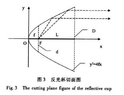
The cut surface of the parabolic reflector is shown in Figure 3. It can be seen that the diameter of the circular surface of the paraboloid at the focal plane is 4f, where: D is the diameter of the reflector, f is the focal length (the distance from the vertex of the parabola O to the focal point F), and L is the parabola. The distance from the focal point F to the light exit port, d is the total length of the reflector. Since the focal length is larger under a certain aperture, the shallower the reflector, the less the effect of collecting light, and considering the size of the light source module ( The outer diameter of the aluminum substrate is 1=56mm), and the influence of the diameter of the reflector on the light distribution when f=16.18.20.22mm is calculated.
In order to determine the optimal size of the reflector, we simulated the relationship between the illuminance and optical efficiency of the reflector at D.40m. In order to make the simulation result closer to the real situation, set the reflectivity of the reflective surface of the reflector. 85%, and the laboratory measured the luminous flux value of the xM-L luminaire 416lm data into the software.
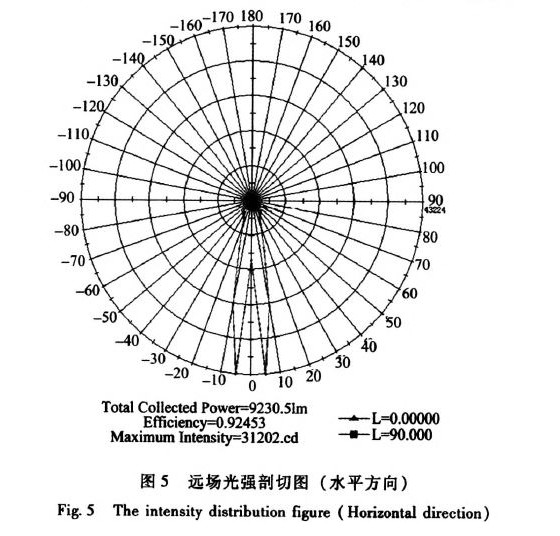
After that, by performing parameter sensitivity analysis on the light exit diameter D and the focal length f, the focal length of the reflector is set to f=16.18.20.22 mm. and the light source array is located in the focal plane: the obtained result is shown in FIG. 4, and the far field intensity section is shown. Cut the picture as shown in Figure 5.
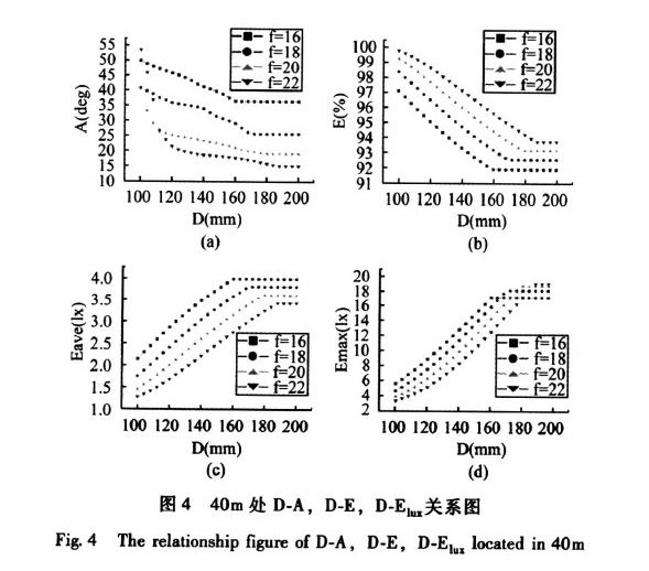
It can be obtained from the analysis in Fig. 5. Under the same focal length, D is inversely proportional to the efficiency E. Under the same D, f is also inversely proportional to the illuminance E. To meet the requirements, the semi-light intensity angle A should be as small as possible, and the illumination at 40m is large enough. The overall length of the reflector is not exceeded. When the final determination is D=180mm.f=20mm, the reflector surface is the best.
However, the half-light intensity angle at this time is too large. As can be seen from Fig. 5, the light intensity has a bimodal phenomenon. Since the software reads the half-light intensity angle, half of the central light intensity is selected by default, but In practice, it is found that the central light intensity is not the maximum value of the light intensity, so it needs to be manually read. Through simulation, when the D=180mm, f=20mm, the half-light intensity angle is about 11.2 degrees, which can meet the requirements. .
After determining D and f, the light distribution analysis is performed on the determined reflector, and the illuminance diagram at 40m is obtained as shown in Fig. 6.

It can be seen from the far-field intensity map that the light intensity is concave, indicating that the light source is not reasonable at the focal plane, and defocus analysis is needed. Before the defocus analysis, the back and forth movement of the light source may be related to the tail of the reflector. Contact occurs, and considering the heat dissipation and the beauty of the lamp, the bottom of the reflector is cut to place the heat sink. The cutting is performed at 3 mm in front and rear of the focal plane and at the focal plane, respectively. The focal movement may lose some of the light energy. Therefore, a cylindrical skin is added to the bottom of the reflector after cutting, the skin length is determined to be 20 mm, and the inner wall reflectance is also set to 85%. At different cutting distances, the light source is separated from the light source. Focus analysis, the illuminance at 40m is obtained. The relationship between efficiency and semi-light intensity angle is shown in Fig. 7.
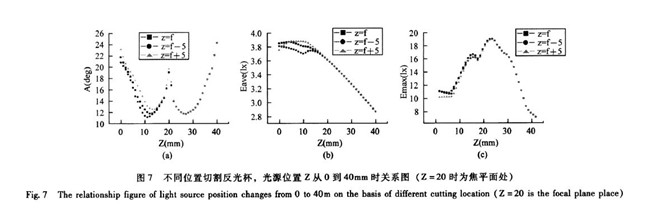
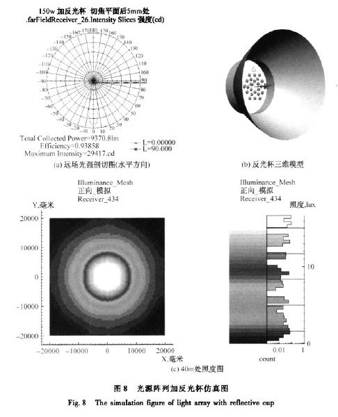
After data comparison, after the bottom end of the reflector is cut off at different positions, the light distribution effect is very small. To meet the half-light intensity angle A at about 15 degrees, and the illumination meets the requirements, finally determine that the cut is 5 mm to the right of the focal plane, and Through the defocus analysis, it is found that the light source array is optimal at z=27mm, that is, 7mm to the right of the focal plane, the half-light intensity angle is the smallest, and the most concentrated light is 11.7 degrees. At this time, the maximum illumination is 16.711x. The intensity cut-out diagram (shown in Figure 8(a)) and the illuminance map (shown in Figure 8(c)) and the final design of the three-dimensional model of the reflector are shown in Figure 8(b).
It can be seen from the analysis that the defocusing of the light source has a great influence on the light distribution effect. Therefore, in the actual processing of the reflector, it is necessary to design a fine adjustment device inside to determine the optimal position.
5 lens optical design
5.1 lens shape determination
There are two main types of optical collimators for LED illumination: the lens and the reflector. The initial light from the LED source will be emitted in the same collimation direction after being fully collimated by the reflector. As can be seen from the above analysis, After the reflector is added to the LED array, the illumination is still not optimal. Therefore, it is necessary to add a lens to the reflector to meet the requirements. The lens material is PMMA, commonly known as plexiglass, which is the best texture of synthetic transparent materials to date. The price is more suitable, the refractive index is about 1.4.
Through geometrical optical analysis, there are two ways to add a lens. The first one is to add a lens at the light exit. The second one is to place the lens in a position inside the reflector in order to avoid the parallel light emitted by the reflector.
According to the first case, add a lens at the light exit port. Keep the front aperture constant, change the curvature of the back aperture, and see the influence of the size of the contrast to determine the optimal curvature. To determine the radius of curvature of the back surface, first the radius of curvature of the back surface and A sensitivity analysis was performed between the maximum illuminance at 40 m (as shown in Figure 9) to determine the optimal optimized starting profile and reduce the optimization time.
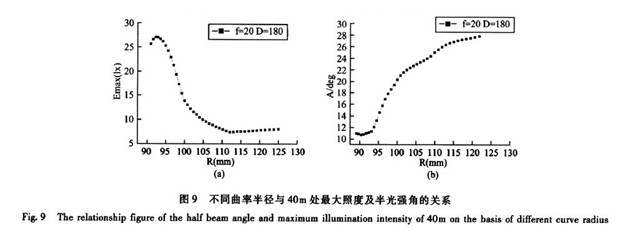
When the radius is R=92.2mm, the maximum illuminance is 27.08blx and the half-light intensity angle is 11 degrees, which satisfies the condition.
5.2 lens position determination
According to the second case, the simulation is first carried out at three positions, and the lens is placed at a distance of 25 mm, 50 mm, and 74.25 mm from the light source. As shown in Fig. 10, the radius of the rear aperture is determined, and the influence of the curvature of the aperture on the illuminance at 40 m is observed after the change. .

In order to avoid the parallel light emitted by the reflector, the edge line L. equation is:
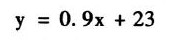
Where: k--slope slope, as L. passes the point (0, 23), (74.25, 90), the linear equation is:
At this time, y is the diameter of the front surface of the lens. The lens is placed at different positions in the reflector, and the relationship between the different radii of curvature and the maximum illuminance is shown in Fig. 11.
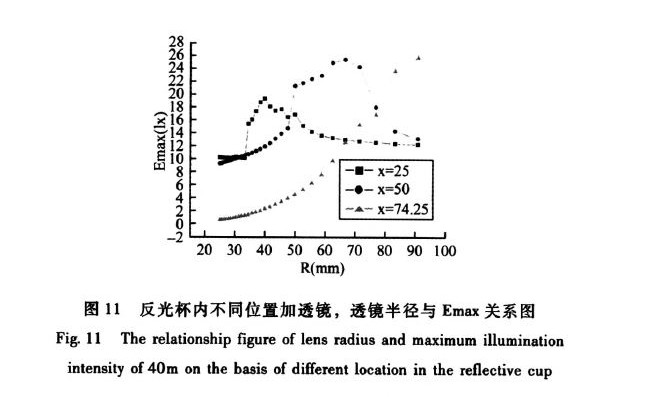
When x=25, the illuminance of R=40mm reaches the maximum, which is 19.3lx; when x=50, when R=66.7mm, the illuminance reaches the maximum, which is 25.3llx.
From the analysis, it is finally determined that when R=92.2mm, the far field illumination value is the largest, which is 27.08lx, which satisfies the illumination requirement, so it is determined that the lens is added at the light exit.
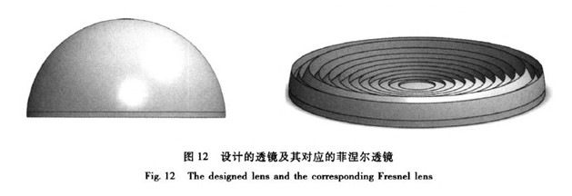
Considering the influence of lens thickness on light energy and processing cost, the lens is made into a Fresnel lens, and its working principle is very simple. Since most of the refractive energy of the lens occurs on the optical surface, remove as much optics as possible. The material, while retaining the curvature of the surface, can achieve the same effect, and the cost is much lower than the ordinary convex lens. Maintain the thickness d = 5mm, the final surface is shown in Figure 12.
6 Summary
This paper introduces a new secondary optical design based on improving the far field illumination of LED, which can provide some basis for the structure and light distribution design of future lamps.
Replacement for traditional Neon lighting of Structure outline such as Roofs, Windows, Doors, Storefronts and Carports *Low power consumption, Super-bright led light running with low temperature *All the light spread and completely smooth, luminous very even *Flexible, Slim, compact and flexible PCB strip. Applicable for bendable or angled patterns, or in continuous rows *Cuttable and linkable. It can be cut in every 1.64ft/0.5m along the cutting marks, without damaging the rest strips *LED Type: High Quality 5050 SMD LED, high intensity and reliability, Long lifespan up to 50,000+ hours
Led Neon Lights,Led Neon Rope Light,Neon String Lights,Led Neon Flex Light
XINGYONG XMAS OPTICAL (DONGGUAN ) CO., LTD , https://www.xingyongled.com