Bus-type automotive digital instrument design based on MC9S12HZ256
Abstract: Firstly, the CAN bus and SAE J1939 protocol are studied, and a bus-type automotive digital instrument solution based on MC9S12HZ256 microcontroller is proposed. The message frame format of the SAE J1939 protocol and the definition of engine-related parameters in the application layer protocol, as well as the processing method of the stepping motor and its driving and vehicle speed signals are introduced in detail. The digital instrumentation system hardware platform consists of a microprocessor and a module for signal acquisition and information processing and display. The software design part of the program realizes the reading and processing of the CAN bus and each sensor data. The system is able to reflect vehicle conditions in real time.
Keywords: automotive digital instrument; MC9Si2HZ256; stepper motor; CAN bus; SAE J1939
This article refers to the address: http://
Automotive instrumentation has undergone mechanical, electrical, analog circuit electronic and all-digital development, and is now in the period of electronic shift from analog circuit to full digital. The vehicle instrument with CAN bus interface collects and processes the sensor's speed, oil quantity, oil pressure and other signals, and reads the engine speed, water temperature and other information according to the SAE J1939 protocol. The é™”-type automobile instrument has the advantages of high indication accuracy, responsiveness, simple structure and high reliability, and represents the development direction of automobile instrument.
1 CAN bus and SAE J1939 protocol
1.1 CAN bus and SAE J1939 protocol introduction Controller area network CAN (Controller Area Network) is a serial communication protocol developed for real-time data exchange between many control units and test instruments. CAN2.0 includes 2. OA and 2.0B two parts. The CAN topology is a bus type, so it is also called a CAN bus. The SAE J1939 protocol is based on CAN2.0B as the network core protocol for network serial communication and control protocols for passenger cars, trucks, agricultural and construction vehicles. The protocol encodes the 29-bit identifier of the CAN extension frame and encapsulates its data information with CAN data frames to form a unique coding system. As a vehicle communication standard, the agreement specifies the address configuration, naming, communication method, and message transmission priority of the internal ECU of the car, and details the specific ECU communication content inside the car. The SAE J1939 protocol standard maximizes the performance of CAN, reduces the number of harnesses, and enables high-speed data transmission between vehicle electronics.
1.2 CAN communication message frame format under SAE J1939 protocol CAN supports four types of message frame transmission information: data frame, remote frame, error frame and overload frame (Overload) Fram-e). CAN has two types of message frames: standard frame and extended frame. The essential difference is the length of the identifier (ID). The ID of the standard frame has 11 bits, and the extended frame has 18 bits. Table 1 shows the data frame structure of the CAN extended format.
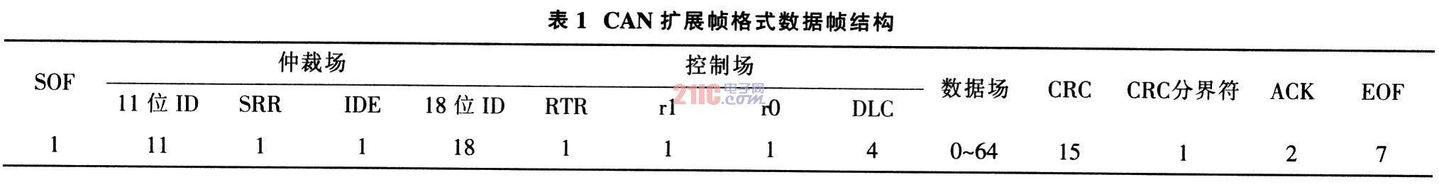
The CAN data frame is divided into the following bit fields: Start Field (SOF), Arbitration Field, Control Field, Data Field, Cyclic Redundancy Check Field (CRC), Answer Field (ACK), and End of Frame (EOF). The control field consists of 6 bits, including the data length code (DLC) and 2 reserved bits r1, r0, which must be dominant bits in the data frame. The DLC is 4 bits, indicating the number of bytes in the data field, encoded as 0-8. The Cyclic Redundancy Check CRC field consists of a 15-bit CRC sequence and a CRC boundary. The CRC range includes the frame start, arbitration field, control field, and data field. The response field (ACK) is 2 bits long and contains the response gap and response delimiter. In the response field, the transmitter sends these 2 bits as recessive bits. When the receiver correctly receives a valid message, it sends a dominant bit to the sender during the answer gap to indicate a response. Each data frame is terminated by a 7-bit recessive level.
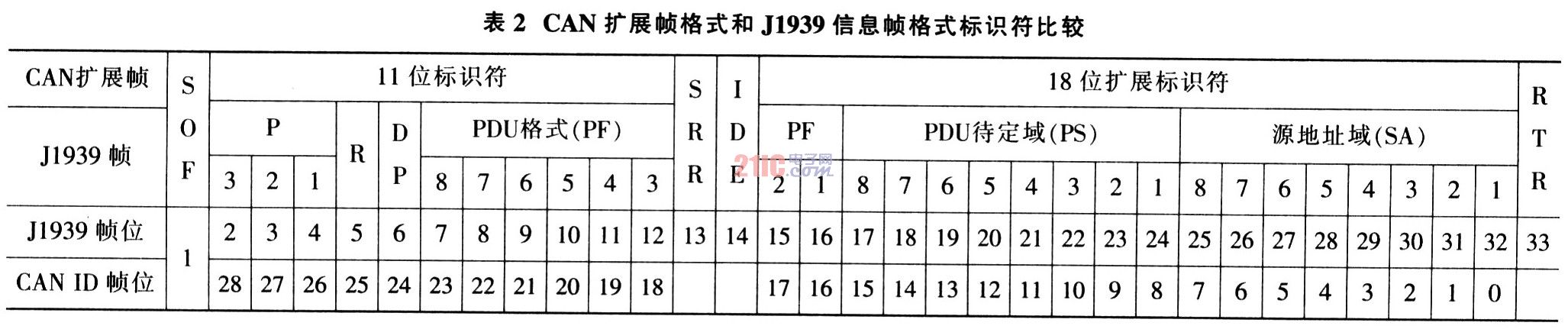
The J1939 protocol supports the CAN 2.0 protocol standard and uses the extended frame format to transmit information in units of messages. Protocol Data Unit (PDU) is a framework defined by the J1939 protocol to organize key information related to the J1939 protocol in CAN data frames. The PDU consists of a priority domain (P), a reserved domain (R), a data page domain (DP), a PDU format field (PF), a PDU specific domain (PS) and a source address domain (SA) constituting an identifier, and a data domain. (Data Field) consists of 7 bit fields. These bit fields correspond to the 29-bit identifier and data field of the CAN extended frame, respectively. Where PS is an 8-bit segment whose definition depends on the PF value. If the PF value is less than 240, PS is the target address (DA); if the PF value is between 240 and 255, PS is the group extension (GE). The comparison between the CAN extended frame format and the SAE J1939 information frame format identifier is shown in Table 2. The definition of the PDU does not include SOF (frame start), SRR (alternate remote request), IDE (identifier extension), RTR (remote request), partial control domain, CRC (check domain), ACK (in the CAN frame). Control fields such as acknowledgment fields and EOF (end of frame) are included because these fields are explicitly defined by the CAN 2.0 specification and are not visible when the OSI model is above the data link layer.
1.3 SAE J1939 Protocol Application Layer The application layer defines parameters such as data length, data type, resolution, similarity and reference label of the J1939 protocol, and assigns a number (SPN) to each parameter. Since the J1939 protocol transmits data in the form of Protocol Data Units (PDUs), one PDU can transmit 8 bytes of data. Therefore, the parameters need to be combined and transmitted. The parameter group is defined in the J1939 application layer protocol, and each parameter group is assigned a number (PGN) as the unique label of the parameter group. The parameter group content includes the update rate of the group parameter, the effective data length, the data page, the PDU format, the PDU to be determined, the default priority, and the specific content of the data field. The CAN data frame under the SAE J1939 protocol standard is illustrated by an electronic engine controller 1 (EECl). J1939 defines Electronic Engine Controller 1 (EECl) as follows:
PGN 61444 Electronic Engine Controller 1
Engine related parameters:
Transmission cycle speed: determined according to engine speed; data length: 8 bytes; data page: 0; PDU format (PF): 240; PDU pending (PS): 3; default priority: 3; parameter group number (PGN) :61444(0xF004)
Starting position Length Parameter name SPN
......
4-5 2 bytes Engine speed 190
......
According to the definition of the SAE J1939 protocol, the PDU encoding of the parameter EECl shall be “OC FO 04 00 XX XX XX XX XX XX XX XX (XX represents arbitrary data)â€, wherein the first 4 bytes are 29-bit identifiers, and the last 8 The byte is the data field, where the 4th and 5th bytes in the data field represent the engine speed. If the data received from the engine control unit is OC F0 04 00 XX XX XX 5D CO XX XX XX, the engine speed can be calculated based on the values ​​of these 2 bytes and the definition in SPNl90:
Engine speed = raw number x resolution + offset = 24 000 (0x5DC0) x 0.125 + 0 = 3 000 r/m.
Similarly, other data required for automotive instrumentation can be calculated according to the definition of J1939. It is then processed by the meter ECU and drives the display unit to accurately display the current vehicle status.
2 Digital Instrument System Design The automotive digital instrumentation system consists of modules such as signal acquisition and processing display. Figure 1 is a block diagram of the bus-type automotive digital instrument using the MC9S12HZ256 microcontroller.
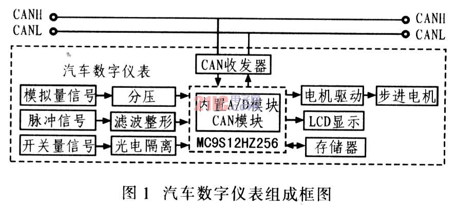
Signal acquisition includes CAN bus data acquisition and sensor data acquisition. Through the analog signal partial pressure, pulse signal filtering and shaping, the switching signal is optically isolated, the microprocessor collects the sensor signal, and at the same time reads the CAN bus signal through the transceiver, then performs signal processing, and then drives the stepping motor through the controller, LCD liquid crystal Screen and other devices. In the actual vehicle environment, the system design follows the SAE J1939 protocol to obtain engine speed, water temperature and fault code information on the CAN bus. The information such as vehicle speed, oil quantity, oil pressure, and brake pressure are in the form of analog quantity and pulse quantity. The sensor reads.
2.1 MC9S12HZ256 Microcontroller MC9S12HZ256 is an enhanced 16-bit microcontroller microcontroller (MCU) for Freescale's MC9S12 series for automotive instrumentation applications. Its integration is high, the on-chip resources are rich, and the functions are powerful. The interface modules include SPI, SCI, FC, A/D, PWM and so on. The enhanced 16-bit S12 CPU is added to the phase-locked loop circuit to generate a clock signal higher than the external crystal frequency. The on-chip bus clock frequency is up to 25 MHz; KB RAM, 2 KB EEPROM; 2 asynchronous serial communication interfaces (SCI), 1 synchronous serial device interface (SPI), 1 FC bus interface (12C); 1 8-channel 16-bit timer (TIM) , a 16-channel 10-bit analog-to-digital converter (ATD), a 6-channel pulse width modulator (PWM), and 2 CAN controller modules (compatible with CAN 2.0 A/B). In addition, this MCU also integrates a 32x4 liquid crystal drive module (LCD). The background debugging mode (BDM) and CodeWarrior development environment of the single chip microcomputer make the peripheral hardware circuit of the bus type automobile digital meter applying the single chip microcomputer relatively simple, and the development process is simple and convenient.
2.2 Stepper motor and its drive Stepper motor is a converter that converts electric pulse signal into corresponding angular displacement or line displacement, and its speed or linear velocity is proportional to the pulse frequency. The stepper motor can directly perform open-loop positioning control with a pulse signal, eliminating the need for a position or speed sensor. The VID29 series stepper motor has a gear train with a reduction ratio of 180/1 and can work under 5 to 10 V pulses. In the microstep mode, one pulse can rotate the rotor by 15°, the corresponding output shaft rotates (1/12)°, and the maximum angular velocity is 600°/s. Each piece of VId66-06 instrument stepper motor driver chip can drive 4 stepping motors at the same time to work in micro step mode. The working principle is shown in Figure 2. Only 2 control signals are required for each stepper motor. On the rising edge of the input signal F (SCX), the motor output shaft is rotated by one microstep, ie (1/12) °, and the input signal "CW/CCW" (clockwise/counterclockwise) controls the steering of the stepper motor output shaft.
2.3 CAN node design The main control device MC9S12H256 integrates the CAN controller supporting CAN2.0A/B, and integrates the physical layer and data link layer functions of the CAN protocol, which can complete the framing processing of data communication, including bit filling. , data block coding, CRC check and priority discrimination. The CAN transceiver PCA82C250 is selected, which is suitable for high-speed (up to l Mb/s) CAN bus data transmission in automobiles. Set the terminating resistor (typically 120 Ω) to the interface between the CAN controller and the physical bus to improve the differential transmit and receive functions of the bus. Figure 3 shows the CAN interface circuit.

2.4 Pulse signal processing The output signal of the Hall type vehicle speed sensor is a rectangular wave. The output signal of the magnetoelectric speed sensor is a sine wave, and the signal frequency is proportional to the vehicle speed. The speed signal is converted into a rectangular wave signal that can be processed by the single chip by the processing circuit, and the measured vehicle speed is measured by the rectangular wave frequency.
The periodic method is to fill one or more cycles of the signal under test with a standard clock signal sequence. The measurement method of the measured signal period is calculated by counting the number of standard clock pulses. The measured signal period is T, the reference time base signal period is Ï„, the standard pulse number is n, and the number of filled signal periods to be tested is N, then:

The measurement error mainly comes from two parts: one part is the relative error dτ/τ of the standard time base. Since the standard time base is generated by the quartz crystal inside the single chip microcomputer, this part of the error is usually below 10-6, which can be ignored. The other part is the counting error dn. /n, the principle of this error is shown in Figure 4.
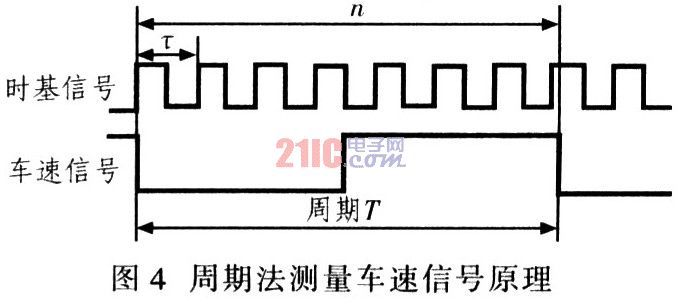
The last positive transition of the time base signal sequence is not within the range of the signal under test to be filled, and the maximum count error that can be produced is -1. This part of the error is small at low speeds and slightly larger at high speeds. Taking the vehicle characteristic coefficient (the number of revolutions of the speed sensor when the vehicle travels per kilometer) is an example of a l 320, 8-pulse vehicle speed sensor with a standard time base signal period of 50 μs and a vehicle speed of 100 km/h. The maximum relative error is 1.47%, and the maximum relative error is 2.64% when the vehicle speed is 180 km/h. It fully meets the basic requirements for the speedometer error in the QC/T727-2004 standard for automobile and motorcycle. Appropriately reducing the time base signal period τ and increasing the N value at high speed can reduce the error. The cycle method calculates the vehicle speed V: 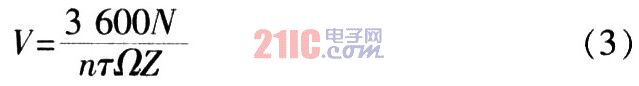
In the formula, Z is the number of output pulses of the wheel speed sensor rotating one revolution; Ω is the vehicle characteristic coefficient, that is, the number of revolutions of the wheel speed sensor per 1 km of the vehicle.
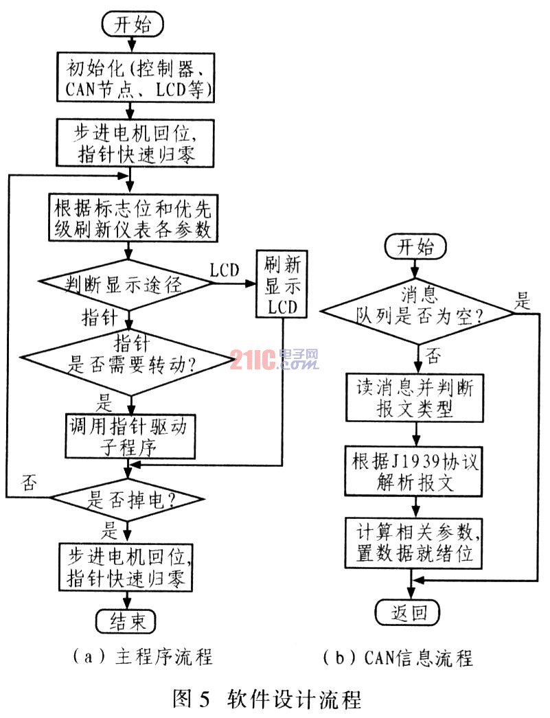
3 software design The main program flow and the process of reading CAN information are shown in Figure 5. The vehicle digital instrument mainly performs functions such as data acquisition, data processing, numerical display and communication with the host computer. The function of this instrument is to continuously receive information and carry out the cyclic process of information transmission, processing, output display and alarm. After booting, the system first initializes the main controller, CAN node, LCD screen, stepper motor, reads the value in the EEPROM and enables CAN interrupt, and sets the CAN mask code and acceptance code. Then enter the main program, each stepper motor returns quickly and the pointer returns to zero. Then collect external signals, calculate vehicle speed, oil pressure and other information and read the message queue on the CAN bus. Calculate the engine speed, water temperature and fault code information according to the J1939 protocol, process the information and control the stepper motor and LCD display.
4 Conclusions The CAN bus communication protocol and SAE J1939 protocol are studied, and the design of automotive digital instrumentation system based on CAN bus is realized. The software design realizes the functions of the automobile instrument. The software design makes full use of the functional modules integrated in the MC9S12HZ256 microcontroller to reduce the amount of peripheral circuit components. The meter is fast in response, accurate in positioning and reliable in operation. With the development of bus technology and the improvement of automotive electronic control requirements by relevant regulations, automotive digital meters based on CAN bus will be more widely used.
The formats of Instax Film give an image size of 46 mm × 62 mm (1.8 in × 2.4 in) for the Mini, 99 mm × 62 mm (3.9 in × 2.4 in) for the Wide and 62 mm × 62 mm (2.4 in × 2.4 in) for the Square. The Instax colour film is available in Mini, Wide, and Square formats and the black and white Instax Monochrome is available in Mini and Wide formats.
Instax Mini is available in colour and black and white, other limited edition also as well. The instax Mini films suit for Instax Mini 7 / 8 / 9 / 70 / 90 / SP-1 / SP-2.
Instax Wide is available in colour and black and white. The Instax Wide Film is compatible with Instax Wide 201 / 300 Instant Camera .
Instax Square Film is compatible with Instax SQ 10 and SP-3.
Instax Film
Instax Film,Fujifilm Instax Film,Instax Pack Film,Fujifilm Camera Film
GuangZhou CAIUL Digital Products CO,.LTD. , http://www.caiul-instax.com