Simulate load switch circuits with different input voltages and loads
Load switches are used in a wide range of applications, from cars to mobile phones, from servers to medical devices, so it's no surprise that everyone uses load switches in different ways. The data sheet can show performance and specifications, but it does not cover all applications. Perhaps the data sheet shows a performance with an input voltage of 1.2V or 1.8V, but your device actually runs at 1.35V. What should you do? Want to know what the specific application will produce? Try TI's WEBENCH® tool.
Open the load switch design in WEBENCH
Before starting the design, please click on the Power Designer Enabled Devices link in the TI WEBENCH Design Center. Select the “Load Switch†option from the top list (see Figure 1). Click on the "Create" button and the WEBENCH tool will open the product page of the selected load switch.

Figure 1: List of WEBENCH load switch devices
The WEBENCH function of the load switch can be implemented by the WEBENCH component on the right side of the product page. Figure 2 shows the components of the TPS22965 load switch.

Figure 2: TPS22965 Product Page Load Switch Assembly
When using this component, some design parameters have been entered into the tool. The left side of the component shows the name of the parameter for the user to enter, and the right side shows the range of values ​​that apply to that particular load switch. Clicking on the "Open Design" button will launch the WEBENCH tool. The result is similar to that shown in Figure 3.

Figure 3: WEBENCH Designer Layout
Change input value
In the upper left corner is the "Change Inputs" console, as shown in Figure 4.

Figure 4: WEBENCH Designer Change Inputs Console
After the design is created, the design parameters can be returned and modified via the "Change Inputs" console. There are other options and parameters that can be modified depending on the selected load switch. By changing these values, the simulated design results are updated accordingly, including design schematics, data plots, run values, and more.
Design schematic
Click on the "SchemaTIc" console and the design schematic will open.
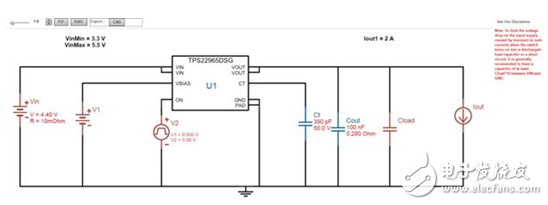
Figure 5: The created WEBENCH design schematic
The design schematic shows the created design based on the input design parameters and load switch configuration. By looking at the circuit diagram, you can check the connections and components used in the load switch.
Running value
The OperaTIng Values ​​console provides a number of calculated values ​​that show the expected operation of the device after considering all of the input design parameters. Figure 6 shows the console example.

Figure 6: WEBENCH Designer "Operating Values" Console
This is one of the most useful consoles in the WEBENCH Designer tool because it tells you what the load switch is expected to run for a particular application. Inrush current, rise time, efficiency, on-resistance, and power dissipation are just a few of the many calculations. To change these values, simply enter the new design parameters in the "Change Inputs" console. Doing so can see how changing the design parameters can change the behavior of the load switch. For example, changing the output capacitance can affect the inrush current of the load switch.
Add a load switch in the "Power Architect"
Your application may have a specific boot sequence depending on the processor or FPGA power rail. When designing power supplies using the WEBENCH Power Architect tool, load switches can be added for the power sequence. For instructions on how to do this, please visit the WEBENCH Help Center.
The unique design brings innovation and success to the market. If your design uses load switches in ways not listed in the datasheet, the WEBENCH tool can help you simulate the run and stay one step ahead!
If your design requires support and assistance, please post the issue to the Texas Instruments Online Support Community Load Switch and Power Path Protection Forum.
Common mode choke coil uses the ferrite core and winds with double wire which has the ability of high common mode noise suppression and low differential mode noise signal suppression. It is difficult to deform in high speed signal and has small working frequency impedance,large interference frequency impedance and small volume.
Application fields
Common mode choke coil can be used to the charging stations, transformers, inductors, sensors, instruments and apparatus, computer host display and communication fields
Electric Component,Small Filter Inductance,Utility Magnetic Core,New Design Transformer
Anyang Kayo Amorphous Technology Co.,Ltd. , https://www.kayoamotech.com