Infineon PMSM motor control system solution
The characteristics of PMSM of permanent magnet synchronous motor determine the complexity of the control system. The more common PMSM motor control system is mainly driven by the driver, main controller (logic control board) and various sensors (current sensor, temperature sensor and resolver winding, etc.) Etc. Figure 2 shows Infineon's solution for PMSM motor control systems on EVs and HEVs:
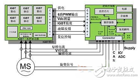
Figure 2 PMSM motor control system
In the scheme shown above, the driver consists of an IGBT three-phase bridge driver board, a HybridPACK2 IGBT (referred to as HP2) module and a DC bus capacitor. The IGBT three-phase bridge driver board includes a 6-channel IGBT pre-driver circuit, a switching power supply SMPS, a logic gate circuit, a fault detection circuit, and a voltage and temperature measurement circuit. The HP2 module consisting of six IGBT units driving the three-phase bridge of the PMSM motor is a high-power module designed by Infineon for EV and HEV applications with a maximum operating voltage of 650 V and a maximum power rating of 80 kW. The maximum operating junction temperature is 150 °C. The main controller is equipped with the minimum system circuit of the 32-bit Infineon 32-bit single-chip microcomputer TC1782 (Audo-MAX series), the resolver decoding circuit, and the monitoring circuit and sensor interface circuit supporting the ISO26262 functional safety solution.
Main chip selectionThe control of the PMSM motor requires that the main controller not only has a powerful dedicated peripheral suitable for motor control, but also has strong real-time performance. The TC1782 is a high-performance 32-bit microcontroller with a Haval architecture and an asymmetric dual core (primary core Tricore and peripheral control coprocessor PCP). The clock speed is up to 180MHz. The built-in floating-point arithmetic unit FPU supports DSP algorithm instructions. 2.5M Byte FLASH, 176K bytes of RAM.
The important peripherals related to motor control of the TC1782 are the general-purpose time array GPTA and digital-to-analog conversion ADC. The GPTA provides a flexible set of timing, comparison and capture functions that can be flexibly combined into a signal detection unit and a signal generation unit for dynamic control of dead time and asymmetry different from edge alignment and center alignment for motor control. PWM output. A digital-to-analog converter module that is triggered by hardware (such as GPTA) and implements synchronous conversion can at least support simultaneous acquisition of two-phase currents in a motor application. Figure 3 shows a single-cycle timing of the motor control. The GPTA generates a complementary PWM waveform with a dead band. At the PWM midpoint, it simultaneously triggers the conversion of ADC0 and ADC1. The ADC module starts the CPU interrupt after completing the corresponding channel conversion. Service program.
Each AD conversion module (ADC0 and ADC1) of the TC1782 supports 16 conversion channels with programmable conversion accuracy (8/10/12 bits) and a minimum conversion time of less than 1 microsecond at 12 bits. The dedicated peripheral control coprocessor PCP can handle most of the interrupt load so that the main core can centrally handle complex operations for motor control, such as Park transform, Clarke transform, and space vector modulation (SVM). At present, TC1782 microcontrollers have attracted more and more attention from auto manufacturers and component suppliers, and have been selected as one of the key components of electric vehicle drive motor controllers by mainstream OEMs and component suppliers at home and abroad.
hardware designAccording to the functions required by the PMSM main controller, the objects actually involved in the control, and the characteristics of the main control chip, the hardware structure of the main controller of the PMSM motor control system is shown in Fig. 4. It adopts functional division and modular design ideas, and is separated into different functional modules according to functional requirements. The main interface technical parameters of the main controller are:
1) 14 analog input channels (12 bits);
2) 6-channel PWM output (with level shifting);
3) 2-way CAN communication interface (support calibration and system communication);
4) Cyclone interface circuit (AD2S1210) that can be configured for parallel or serial communication;
5) Digital input (fault detection and diagnosis, etc.);
6) Digital output (emergency stop control and main relay control, etc.);
7) Power system.
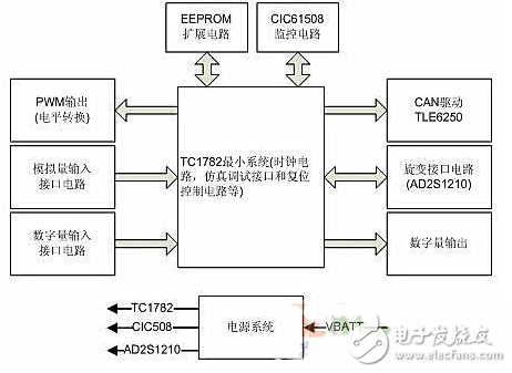
Figure 4 main controller hardware structure
The PMSM motor control system requires a high level of safety, and the driver has strict requirements on the fault response time of the main controller. Therefore, the main controller adopts the monitoring chip CIC61508 designed to meet the ISO26262 functional safety specification to design the monitoring circuit. The CIC61508 has configurable voltage monitoring inputs, configurable main CPU task execution time and configurable fault response time and output. It can monitor the power of the main CPU and software running status in real time, and control other fault response output according to pre-configured. The IC's enable and reset pins enable the system's functional safety requirements.
software designThe control system scheme of PMSM motor is mainly based on field-oriented FOC control (Fig. 5). In addition, in order to achieve the best control effect, several control schemes are often used together, such as the principle of maximum torque control and field weakening control (Fig. 6). In order to achieve the optimal efficiency of the motor and a wide range of speed control schemes, the torque control and PWM control are integrated in one control scheme.
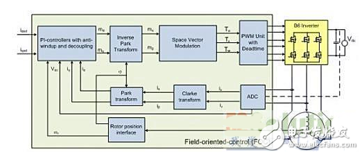
Figure 5 Field Oriented Control FOC
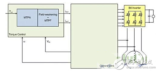
Figure 6 Torque control and field weakening control
The PMSM motor control system schemes in Figures 5 and 6 show that in addition to the FOC-related calculations, such as Clark, Park, i-Park, and SVM [4] calculations, the TC1782 requires some signal acquisition from the system. Such as phase current, bus voltage, motor position and speed. In addition, considering the main controller's participation in system communication and functional safety requirements, these will be a serious challenge to the single-core CPU load. Based on the above factors, according to the functional requirements of the main controller, the software development of the main controller is modularized and distributed to the main CPU of the TC1782 and the peripheral coprocessor PCP, thereby forming a software flow structure framework as shown in FIG.
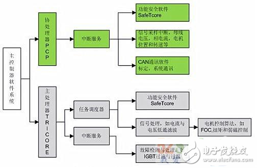
Figure 7 main controller software system architecture
In the software system architecture shown in Figure 7, the main CPU calls Infineon's safety function software SafeTcore and PMSM motor control related algorithm software on the basis of a small task scheduler. SafeTcore detects the failure of the system during CPU operation. The test project can be configured as required, and the PMSM motor control algorithm that is run is performed using the control strategies shown in FIGS. 5 and 6. In addition to running the safety function software SafeTcore software to monitor the operation of the main CPU, the peripheral coprocessor PCP can also handle communication-related interrupts and signal sampling interrupts, thereby reducing the interrupt load of the main CPU.
Software's resolve decodingAs mentioned earlier, PMSM motor position and speed information is important in motor control, and the resolver interface circuit provides a hardware solution for obtaining this information. From the perspective of the redundancy of the control system required by the ISO26262 automotive functional safety specification, it is necessary to provide a second way to obtain the motor position and speed information to verify whether the information obtained by the hardware solution is correct and improve the safety of the system. Electric vehicle motor control systems often use software's resolver decoding as a backup to the hardware decoding scheme. The high-speed FADC interface of the TC1782 provides the hardware foundation for this method. The specific idea is shown in Figure 8:
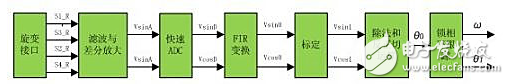
Figure 8 Software decoding of the resolver signal
The FIR transformation shown in the figure above and the module functions behind it are all done by software. The CPU calculation speed is very important for real-time control systems such as PMSM. Many tests have found that the TC1782 software code generated based on the above software decoding process can achieve a computational speed of 5 microseconds, and the efficiency can meet the application requirements of the system.
Test verificationThe test of the PMSM motor control system is carried out on the AVL motor test bench. The physical and system architecture is shown in Figure 9. The bus voltage and input power are shown in Yokogawa's WT3000 power analyzer test, the current sensor detects U-phase and V-phase currents, and the WT3000 power analyzer tests the PMSM motor's output torque and speed through a torque sensor and tachometer.
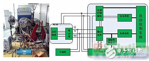
Figure 9 Motor Test Bench System
Figure 10 shows the phase current and current frequency of the bus voltage of 230 volts and different power supply output power. The left figure shows the effective value of the 26 kW lower phase current is 235 amps, the frequency is 100.75 Hz, and the right picture shows the 51 kW lower phase current. The effective value is 270 amps and the frequency is 164.8 Hz.
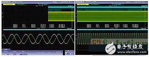
Figure 10 high power test
ConclusionThe electric vehicle motor control system is the core component of the electric vehicle. This paper has carried out the following design and development work for the main controller of the PMSM motor control system:
1) According to the control requirements of the electric vehicle power system, the design principle and function division of the motor main controller are proposed. On this basis, the hardware structure and interface of the main controller based on TC1782 are determined.
2) According to the ISO26262 safety function specification, the SafeTcore functional safety software package is integrated on the hardware of the TC1782 and CIC61508 functional safety monitoring chips.
3) The test shows that the main controller can adapt to the application environment of the electric vehicle and reach the design goal of effective control and management of the whole vehicle power system.
Suzhou Ribao Technology Co. Ltd. , https://www.ribaoeurope.com