Causes of zero drift and common suppression methods
There are many reasons for zero drift, and any component parameter variation (including fluctuations in the voltage source voltage) will cause the output voltage to drift. Practice has proved that temperature change is the main cause of zero drift and the most difficult factor to overcome. This is because the conductivity of semiconductor components is very sensitive to temperature, and the temperature is difficult to maintain constant.
When the ambient temperature changes, it will cause changes in the transistor parameters, so that the static operating point of the amplifying circuit changes, and because the interstage coupling uses direct coupling, this change will be amplified and transmitted step by step, and finally the voltage at the output will occur. drift. The more the number of direct-coupled amplifying circuits, the larger the amplification factor, the more severe the zero-point drift, and the zero-level drift of the first stage is the greatest in the zero-point drift generated at each stage. The key to reducing the zero-point drift is to improve the amplification. The performance of the first stage of the circuit.
Causes and solutions for zero driftIn the actual circuit, different measures can be taken to suppress the zero drift according to the specific situation. The commonly used measures are as follows:
1, choose high quality silicon tube
The Icbo of silicon tubes is orders of magnitude smaller than the manifolds, so currently high-quality DC amplifier circuits use silicon tubes. In addition, the manufacturing process of the tube is also very important. Even if the same type of tube, such as the process is not strict enough, the semiconductor surface is not clean, which will increase the degree of drift. Therefore, qualified semiconductor devices must be strictly selected.
2. Method of temperature compensation
The effect of temperature on the nonlinear components is used to counteract the effect of temperature on the transistor parameters in the amplifier circuit, thereby reducing the zero drift of the circuit. This method is relatively simple, and it is applied more in linear integrated circuits, but the degree of compensation is not ideal. Inspired by the temperature compensation method, people use two transistors with the same model and characteristics to compensate, and receive a better effect of suppressing zero drift. This is the differential amplifier circuit.
3. Modulation method
The guiding idea of ​​this method is to first convert the DC signal into a higher frequency AC signal (this method is called modulation), and then convert it into a DC signal after being amplified by the RC coupling amplifier circuit. The conversion is called demodulation). Therefore, this method both amplifies the input signal and suppresses zero drift.
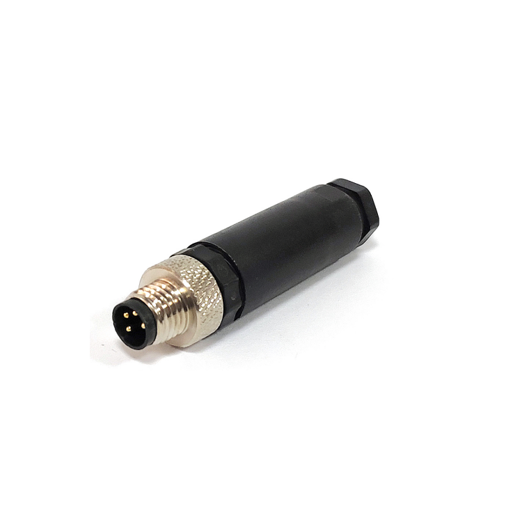
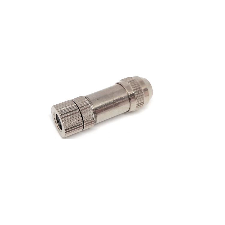
SVLEC field wireable M8 connectors include male , female , straight , angle , 3 4 pins , screw terminal make it easier to wiring with cable. IP67 protection make it durable . And also we have shielded and unshielded type .


M8 Connector,M8 Male Angled Connector,Wireless M8 Connector,3 Pin Female Connector,M8 4 pin connector
Kunshan SVL Electric Co.,Ltd , https://www.svlelectric.com