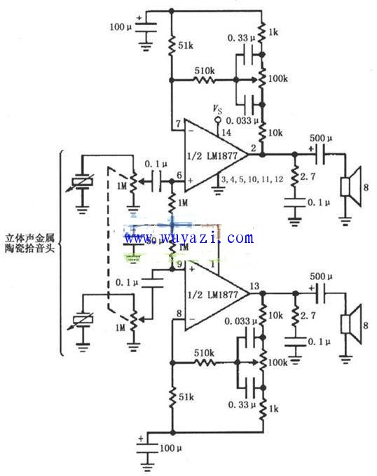
Power amplifier circuit diagram with bass control
As shown in the figure, the stereo phono amplifier circuit with bass control is composed of LM1877. The stereo cermet pickup picks up the stereo left and right channel audio signals on the turntable. After two 1MΩ potentiometer inputs, they are respectively coupled to the input terminals 6 and 9 of the LM1877 by two 0.1μF capacitive couplings. The 13 pins are output separately and sent to the left and right channel speakers respectively.
Among them, two 1MΩ potentiometers are volume potentiometers, and two potentiometers are linked to adjust the volume. Two 1MΩ resistors connected to pin 1 are used to set the amplifier's DC bias operating point and a 0.1μF coupling capacitor to form the input high-pass filter. The 100kΩ potentiometer connected to the feedback loop between pin 2 and pin 7 of the amplifier (samely, the 100kΩ potentiometer connected to the feedback loop between pin 13 and pin 8 of the amplifier) ​​is a bass control potentiometer.
A 2.7 Ω resistor in parallel with the left and right channel speakers and a 0.1 μF capacitor are used to filter out high frequency noise.
An electronic clock device with a wireless network monitoring camera is characterized in that it comprises an electronic clock device body with a wireless network monitoring camera; the electronic clock device body with a wireless network monitoring camera is composed of a foot, a wireless transmission module, a It consists of a rechargeable battery, a speaker, a touch display screen, a camera, a casing, an infrared device, and a microprocessor; the feet are fixedly installed at the bottom of the rechargeable battery; a casing is fixedly installed on the top of the rechargeable battery, and the The interior is provided with a touch screen, a camera, an infrared device and a microprocessor; the microprocessor is electrically connected to the rechargeable battery through wires; the wireless transmission module, speaker, display, camera and infrared device are connected to the micro processor through wires The display screen is arranged at the bottom of the camera, and the camera is surrounded by an infrared device; the wireless transmission module is fixedly installed on both sides of the rechargeable battery, and the speakers are opened on both sides of the casing
Wifi Electronic Clock,Wifi Electronic Clock hidden camera,hidden camera wifi,hidden camera wireless,spy camera wifi
Jingjiang Gisen Technology Co.,Ltd , https://www.gisentech.com