Circuit diagram for testing cable breakage with a single probe
This article will introduce a circuit diagram that uses a single probe to test if the cable is broken. Components such as the 4060 form a 20 kHz oscillator, and the connected lOOkfl and 200pF RC components can change this frequency. Each output of the IC's Q3, Q4, etc. can drive a light-emitting diode or a piezoelectric buzzer to provide the necessary indication. This circuit is mounted in a metal case. Hold the cable with one hand and the tester with the other hand, and sequentially touch the pins of the cable with the probe. If this pin is connected, the stray capacitance will reduce the pitch frequency. Perform the same test on the other end of the cable. The break should be at the end of the frequency that is least affected by stray capacitance. The probe is in contact with one pin of the cable, and the other hand holds the other end of the cable for one-to-one inspection. If the cable is intact, the oscillator will stop oscillating. The short circuit between the motor and the internal coil of the large inductor can also be checked by comparison with each other. A single probe is used to test the multipass, break or not and indicate which end is broken, as shown in the figure below. 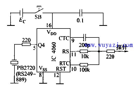
Organize your cabling
- Organizes all types of cables
- Ideal for network Patch Panel cabling
- Finger duct design allows easy cable organization
- Cable pass-through holes in the back of the duct
- Only set up 1U rack
- Work with threaded, round and square hole racks
- EIA 19" RACK standard compliable
- Including screws and mounting hardware
Metal Cable Management,1U Metal cable management,stainless steel cable management,metal cable tie mount
NINGBO UONICORE ELECTRONICS CO., LTD , https://www.uonicore.com