Automotive ADAS and switching converter knowledge sharing
By 2020, the ADAS market is expected to reach $60 billion [source: Allied Market Research]. This means that during the period from 2014 to 2020, the compound annual growth rate is 22.8%. Obviously, this means a huge opportunity for semiconductor products!
ADAS is an acronym for "Advanced Driver Assistance Systems" and is often seen in many new cars today. Such systems are often convenient for safe driving, and if the system detects a risk from surrounding objects, such as unruly pedestrians, cyclists or even other vehicles in unsafe directions, an alert is issued to the driver. In addition, such systems typically provide dynamic functions such as adaptive cruise control, blind spot detection, lane departure warning, driver sleep monitoring, automatic braking, traction control, and night vision. Therefore, in the second half of the current decade, consumers' increasing attention to safety, the need for driving comfort, and increasing government safety regulations have become the main drivers of automotive ADAS growth.
This growth is bound to be accompanied by challenges to the industry, including price pressure, inflation, and the complexity and difficulty of testing such systems. In addition, Europe is one of the most innovative automotive markets, which should not be surprising. Therefore, Europe has seen that ADAS is entering the market, and customers in the European automotive industry are using ADAS in large quantities. However, American and Japanese automakers are not very backward. The ultimate goal of the automotive industry is to provide self-driving cars that are not sitting behind the wheel!
System challengesIn general, the ADAS system includes a processor to collect input data from a myriad of sensors in the car and then process the data so that it can be easily provided to the driver in an easily understandable manner. In addition, such systems are typically powered directly from the car's main battery and have a nominal voltage of 9V to 18V, but may be as high as 42V due to voltage transients in the system and as low as 3.5V in cold crank conditions. Therefore, it is clear that any DC/DC converter in such systems must be capable of handling a wide input voltage range of 3.5V to 42V.
Many ADAS systems use 5V and 3.3V rails to power a variety of analog and digital IC products. However, the processor I/O and core voltages typically require operating conditions below 2V, and may be as low as 0.8V. In addition, such systems are often installed in places where there is limited space and heat dissipation in the car, thus limiting the use of heat sinks for cooling applications. Although high voltage DC/DC converters are commonly used to generate 5V and 3.3V rails directly from the battery, in today's ADAS systems, switching regulators must be switched at 2MHz or higher instead of less than 500kHz in the past. Switching frequency. The key driver behind this transformation is a solution that requires a smaller footprint while remaining above the AM band to avoid any potential interference.
Finally, it seems that the designer's mission is not complicated enough, they must also ensure that the ADAS system meets the various anti-noise standards in the car. In automotive environments, low heat dissipation and high efficiency are important in some areas where switching regulators are replacing linear regulators. In addition, switching regulators are typically the first active component on the input power bus and therefore have a large impact on the EMI performance of the entire converter circuit.
There are two types of EMI radiation: conductive and radiative. Conductive radiation relies on wires and traces that connect the product. Since this noise is limited to specific terminals or connectors in the design, as already mentioned, with good layout or filter design, it is often ensured that the conduction type is met at a relatively early stage of the development process. Radiation requirements.
However, radiated radiation is quite another matter. Everything that carries current on the board radiates an electromagnetic field. Each trace on the board is an antenna, and each copper plane is a resonator. In addition to a pure sine wave or DC voltage, any signal produces noise across the signal spectrum. Even after careful design, the power supply designer never knew how severe the radiated radiation would be before the system was tested. Moreover, the radiation type radiation test cannot be formally performed until the design is fundamentally completed.
Filters are often used to attenuate noise levels at a certain frequency or range of frequencies to reduce EMI. By adding metal shielding and magnetic shielding, the energy that propagates through the space (radiation type) can be attenuated. By adding ferrite beads and other filters, you can control which part of the energy that depends on the PCB trace (conducting type). EMI cannot be completely eliminated, but can be attenuated to a level acceptable to other communication and digital components. In addition, several regulatory agencies require certain standards to be implemented to ensure compliance with EMI requirements.
New input filter assemblies with surface mount technology offer higher performance than through-hole assemblies. However, this improvement is slower than the increased operating frequency of the switching regulator switch. Increased switching speeds result in increased efficiency, shorter turn-on and turn-off times, but increased harmonic components. For every doubling of the switching frequency, EMI deteriorates by 6dB when all other parameters such as switching capacity and switching time remain constant. Broadband EMI behaves like a first-order high-pass filter, and if the switching frequency is increased by a factor of 10, the radiation is increased by 20dB. A skilled PCB designer will design a small thermal loop and use a shield ground plane as close as possible to the active layer. However, the device pin layout, package structure, thermal design requirements, and package size required to store sufficient energy in the decoupling component determine the minimum size of the thermal loop. To complicate matters, in a typical flat-panel printed circuit board, magnetic or transformer-type couplings above 30 MHz between traces will completely weaken the filter because the higher the harmonic frequency, the unwanted magnetic coupling It becomes more effective.
Dual DC / DC converter with low EMI / EMC radiationDue to the above application limitations, Linear Technology (currently acquired by ADI) developed the LT8650S, a dual output monolithic step-down converter capable of accepting high input voltages with low EMI/EMC radiation. Its 3V to 42V input voltage range makes the device ideal for automotive applications including ADAS. Automotive applications must stabilize cold-start and stop-start conditions with minimum input voltages as low as 3V, and load dump transients exceeding 40V. . As can be seen in Figure 1, this is a two-channel design consisting of two high-voltage 4A channels that provide voltages as low as 0.8V, enabling the device to drive the currently available and lowest voltage microprocessors. Kernel. Its synchronous rectification topology provides up to 94.4% efficiency at 2MHz switching frequency, while Burst Mode®) operates with quiescent current below 6.2μA under no-load standby conditions (both channels are on), The device is ideal for always staying connected to the system.
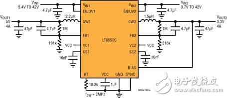
Figure 1: Schematic of the LT8650S - 5V/5A and 3.3V/4A Output at 2MHz
The LT8650S's switching frequency can be set from 300kHz to 3MHz and can be synchronized to this range. Its 40ns minimum turn-on time allows 16V IN to 2.0V OUT buck conversion at 2MHz switching frequency in the high voltage channel. Its unique Silent Switcher® 2 architecture uses two internal input capacitors and internal BST and INTVCC capacitors to minimize thermal loop area. The LT8650S is designed with a well-controlled switch edge and an internal structure with an integral ground plane and a copper post instead of a bond wire, thus significantly reducing EMI / EMC emissions. See Figure 2 for the radiation output characteristics. This improved EMI / EMC performance is insensitive to board layout, simplifying design and reducing risk, even when using two-layer PC boards. The LT8650S easily meets the automotive CISPR 25 Class 5 peak EMI limit when switching at 2MHz switching frequency over the entire load range. Spread spectrum frequency modulation can also be used to further reduce EMI levels.
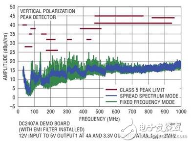
Figure 2: Radiated EMI diagram of the LT8650S
The LT8650S uses an internal top and bottom high efficiency power switch that integrates the necessary boost diodes, oscillators, control and logic circuitry on a single chip. The low ripple burst mode operation maintains high efficiency at low output current while maintaining output ripple below 10mVp-p. Finally, the LT8650S is available in a small, thermally enhanced 4mm x 6mm 32-pin LGA package.
in conclusion
It goes without saying that the penetration of the ADAS system in the automotive market will not end soon. In addition, it is clear that finding a power conversion device that satisfies all necessary performance criteria to not interfere with the ADAS system is not a simple task. Fortunately, for designers of this type of system, the Power Products Division of Linear Technology (now part of Analog Devices) offers "best-in-class" power converters that greatly simplify these designs. The task of the division, while eliminating the need for complex layouts or design methods, provides designers with all the performance they need.
Right Angle D-sub Connector IP66 IP67 Rated
IP66 / IP67 waterproof d-sub connectors-Designed for IP Performance
ANTENK has developed IP66 / IP67 waterproof d-sub connectors that utilize a proprietary sealing technology, which maintains the same physical size and footprint as standard d-sub products.
Antenk's line of Waterproof d-sub connectors utilize an innovative sealing technology eliminating the need to redesign enclosures and PC boards when implementing IP67 design upgrades.These connectors are designed for applications that require protection from heavy spray or are exposed to short-term submersion. Connectors are available in vertical and right angle board mount types as well as solder cup for panel mount cable applications. Standard D-Subs are available in 9 pin, 15 pin, and 25 pin positions, and high density D-Subs are available in 15 pin, 26 pin, and 44 pin positions
Applications of Antenk waterproof d-sub connectors:
Hand held computers, scanners, and printers that are used outdoors
Remote sensors, gauges, and data loggers that are used outdoors
Industrial and Medical equipment that is routinely subject to wash down
Transmitters and emergency beacons that are subject to temporary submersion
Gas, Electric, and Water metering systems that have embedded Smart Grid electronics
Portable electric generation equipment (Gen Sets)
Consumer and Commercial boating electronics (Radios, Scanners, Radar, DC Power Ports)
IP67 D-SUB | WATERPROOF CONNECTORS FEATURES & BENEFITS
Signal / Low Power in 6 standard size
(Standard: 9 pin, 15 pin, 25 pin; High Density: 15 pin, 26 pin,44 pin)
Combo-D / High Power in a variety of configurations:
(3W3, 5W5, 7W2, 9W4, 11W1, 13W3, 13W6, 17W2, 21W1, 21WA4)
Solder Cup, Vertical Mount & Right Angle Board Mount Options
High Reliability Screw Machined Contacts
3 amp / 5 amp / 20 amp / 40 amp Power Options
-65°C to +105°C Operating Temperature Range
Right Angle D-SUB Connector IP66 IP67 Rated available in
3 industry sizes/positions:Standard Density (9 pin, 15 pin, 25 pin).
Male & Female Versions
Right Angle D-sub Connector IP66 IP67 Materials
Shell: Steel with Nickel Plating.
Insulator: Glass-filled thermoplastic. U.L. rated 94V-O
(260° process temp for board applications)
Machined Contacts:
Male Pins - Brass
Plating: Gold Flash on entire contact.
IP67 Right Angle D-Sub Seal: Proprietary Information
Right Angle D-Sub IP67 Rated,Right Angle D-Sub Waterproof,Standard Density Waterproof Right Angle D-Sub Connector, High Density Waterproof Right Angle D-Sub Connector
ShenZhen Antenk Electronics Co,Ltd , https://www.antenkconn.com