Advanced microcontroller bus structure perfect analysis
Advanced Microcontroller Bus Architecture (AMBA) defines the communication standard for high performance embedded microcontrollers. The RISC processor can be integrated into other IP cores and peripherals. It is a "digital glue" that effectively connects IP cores and is an important component of the ARM reuse strategy. It is not the interface between the chip and the peripheral, but the interface between the ARM core and other components on the chip. For example, Xilinx's Zynq chip is the connection path between ARM and FPGA.
AMBA3.0 agreement:
1 Advanced High-performance Bus (AHB)
The AHB bus is used for high performance, high clock operating frequency modules. AHB plays a key role in the high performance of the system in the AMBA architecture. AHB is a high-performance processor with on-chip memory, off-chip memory interface, and bridged slow peripherals. High performance, data transmission, multi-bus master controller, burst continuous transmission, step-by-step transmission.
The AHB bus protocol is AMBA's next-generation bus protocol and supports a variety of high-performance bus master controllers.
characteristic:
a burst continuous transmission
b step by step transmission
c Support multiple host controllers, single-cycle master controller processing
d single clock edge operation
e non-tri-state operation
f Support 64-bit, 128-bit bus
g Supports the transfer of bytes, nibbles and words.
The AHB bus allows one or more master controllers to exist on the bus through DMA and DSP. Although slow peripherals can be attached to the APB bus, some slow peripherals are also allowed to be attached to the AHB as slaves, but they are usually attached to the APB bus.
The AHB bus is usually designed to include the following devices:
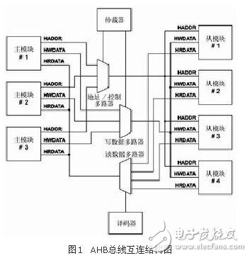
a AHB master controller: The master controller can perform initialization, read and write operations through address and control information. At the same time, there can only be one master controller on the bus.
b AHB slave device: A slave device is usually a passive device that responds to read and write control operations issued by the master controller in its address space. Through the success of the operation feedback to its main controller, the data transmission control is completed.
c AHB arbiter: The arbiter ensures that only one master controller has bus control authority at the same time on the bus, depending on the user's configuration. There can only be one arbitrator on the AHB bus.
d AHB decoder: The decoder parses the address and control information transmitted on the bus. There can only be one decoder on the AHB bus.
2 Advanced System Bus (ASB)
The ASB bus is primarily used for high performance system modules. The ASB is an optional system bus for chip designs that can be used for high performance features not required by AHB. ASB also supports high-performance processors, on-chip memory, off-chip memory provides interfaces and slow peripherals. High performance, data transfer, multi-bus master controller, burst continuous transmission. The ASB bus is a high-performance bus protocol located on the APB bus architecture. It has the following features:
a burst continuous transmission
b single pipe data transmission
c multi-bus master controller
3 Advanced Peripheral Bus (APB)
The APB bus is used to provide bus technology support for slow peripherals.
APB is an optimized, low-power, streamlined interface bus that can be used to technology a variety of different slow peripherals. Since APB is the first bus interface proposed by ARM, APB can bridge every system bus under ARM system. Low power consumption, addressing control, support for simple interface protocols, support for a variety of peripherals. The APB provides a basic microcontroller secondary bus by bridging a high-bandwidth, high-performance bus. Usually, the bus has the following features: support for the mapping register interface, no high bandwidth requirements, and programming to implement peripherals. control.
The APB bus interface protocol is part of the AMBA protocol hierarchy and is a highly optimized thin interface for connecting low-power peripherals.
The APB appears to be a local secondary bus interface protocol that acts as a slave interface to the AHB, ASB bus protocol.
The APB bridge is used by the controller module to ensure efficient transmission of different bus data and forwarding of control signals on different buses.
The APB should be used to connect peripherals that have low bandwidth and do not require high performance data transmission. The latest APB bus protocol specifies that all signal transmissions occur on the rising edge of the clock. This design has the following advantages:
a Easy to achieve high frequency operation
b performance is independent of the mark-space raTIo of the clock
c Simplify static timing with a single clock operation
d no special consideraTIons are required for automaTIc test inserTIon
e Many ASIC libraries have better options in the rising edge registers
f Simplified integrated clock simulator
The above advantages also show that the APB bus can better link to the latest AHB bus interface.
The APB bus protocol includes an APB bridge that converts the control signals on the AHB, ASB bus to the available signals on the APB slave controller. All peripherals on the APB bus are slaves. These slaves have the following features:
a Receive valid address and control access
b When the peripherals on the APB are inactive, they can be placed in a 0-power state
c Decoder can provide output timing (non-locking interface) by strobing signal
d can perform data writing when accessing
APB is mainly used for connection between low-bandwidth peripheral peripherals, such as UART, 1284, etc. Its bus architecture does not support multiple main modules like AHB. The only main module in APB is APB bridge. Its features include: two clock cycles of transmission, no waiting cycles and response signals, simple control logic, and only four control signals. The transmission on the APB can be illustrated by a state diagram as shown in FIG.
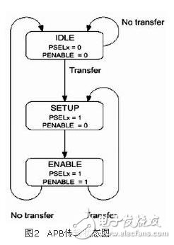
1) The system is initialized to the IDLE state. There is no transfer operation and no slave modules are selected.
2) When there is a transfer to be made, PSELx=1, PENABLE=0, the system enters the SETUP state and will only stay in the SETUP state for one cycle. When the next rising edge of PCLK arrives, the system enters the ENABLE state.
3) When the system enters the ENABLE state, the PADDR, PSEL, and PWRITE in the SETUP state are maintained unchanged, and PENABLE is set to 1. The transfer will only be maintained for one cycle in the ENABLE state and will be completed after the SETUP and ENABLE states. Then if there is no transmission to proceed, it enters the IDLE state to wait; if there is continuous transmission, it enters the SETUP state.
STF274 Series Brushless AC Alternator
STF274 Series Alternator Suppliers
1.Easy to be connected with power network or other generators. Standard 2/3 pitch windings
check excessive midline current.
3.Balanced rotor with single or two sealed ball bearings
4.Wide range of Flange adaptor and single bearing coupling disc
5.Convenient installation and maintenance with easy access to terminals, rotating diodes andcoupling bolts
6.Meet leading standards


Brushless Dynamo,Three Phase Generator,Stamford Brushless Dynamo Generator,STF274 Series Brushless AC Alternator
FUZHOU LANDTOP CO., LTD , https://www.landtopco.com