Word Clock Synchronization Theory in Digital Audio Systems
The basic theory of 1 word clock synchronization
This article refers to the address: http://
In order to cope with the challenges brought by the high-definition era and meet the production conditions of surround sound, all major domestic TV stations have adopted a fully digital audio system in HDTV studios and OB vans that have been put into use . Therefore, it is necessary to clarify some basic theories about the way the word clock is synchronized.
1.1 Word Clock Synchronization Mode
The most common synchronization method from the analog era is the Time Code (TC code) synchronization method, that is, in a audio system, a unified time code is determined, and all devices are based on this time code, from the same The time point starts to play back or record. The timecode scale displayed on all devices is identical throughout the process. This type of synchronization has also been used in digital audio systems to this day.
The word clock synchronization method can only be used in digital audio systems. The Word Clock is seen as a pulse signal that is used to coordinate digital audio signals of different sampling frequencies and communicate in the same system.
The word clock signal has an accurate and stable sampling frequency, which ensures that in all aspects of the digital audio system, the transmitting and receiving ends of the signal operate at the same sampling frequency, and the bits in the transmitted and received signals start simultaneously. Under the action of the word clock signal, each device in the system achieves frequency synchronization and phase synchronization, and can continue to work normally under stable conditions.
The word clock synchronization mode plays an important role in stabilizing the transmission quality of digital signals in the system. However, when there is a problem with the system's word clock synchronization state, which leads to severe degradation of signal quality (such as the transmission of a word clock signal, which causes sudden noise in the system), it is sometimes overlooked from the direction of the word clock. To solve the problem. This is because the effect of this synchronization method in actual operation is not as intuitive as the time code synchronization method.
1.2 Setting the system's word clock synchronization status
To implement the word clock synchronization status of a digital audio system, one (and only one) word clock signal generation source must be set in the system. In fact, digital audio devices such as digital mixers and digital audio workstations can generate word clock signals internally, but only one word clock signal generation source can be set in each digital audio system. This is because the word clock in each device. The signal determines the sampling frequency in this device. If different word clock signals appear in one system, it means that the sampling frequency in this system is not uniform, and it will not reach the synchronous working state, which will cause noise and other problems. Therefore, when using a digital audio system, the first step should be to select one of the devices and set it as the source of the word clock signal in this system, that is, the synchronization host. The word clock signal generated in the sync master is referred to as the master clock of this audio system.
In practice, a dedicated word clock signal generator or digital audio mixer, digital audio workstation is usually selected as the synchronization host (MaSTer) in the system. The synchronization mode of the device selected as the host is set to "internal", and the word clock signal generated internally by the host is transmitted to the slave devices (Slave) that need to be synchronized as the master clock of the entire system. The synchronization mode of each slave device in the system is set to "external", and it is ensured that each slave device can stably receive the word clock signal from the host. When the entire system reaches the synchronization state, all the slaves in the system will work according to the sampling frequency determined by the master clock of the master.
1.3 Word clock signal transmission in the system
The word clock signal can be transmitted in two ways.
(1) Directly transfer the word clock signal from the sync master to the slave using the coaxial cable of the BNC connector
In this manner, the word clock signal transmission structure in the digital audio system can adopt a star structure or a daisy chain structure.
In the star structure shown in Figure 1, the word clock signal of the host is output by the host's word clock signal dedicated output interface WC Out, and then transmitted to the slave's word clock signal dedicated input interface WC In through a signal distribution amplifier. . At this time, each slave in the system independently receives the word clock signal from the host without mutual interference.
  
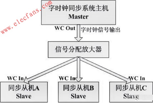
Figure 1 Star structure.
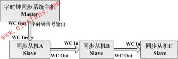
In the daisy-chain structure shown in Figure 2, the word clock signal of the host is output from the dedicated clock output signal interface WC Out of the host, and is directly input to the dedicated input interface WCIn of the word clock signal of the slave A, and then continues to follow this rule. Transfer to the next stage until the word clock signal is input to the WC In of the last slave in the system.
The daisy chain structure has certain disadvantages compared with the star structure, because in this signal transmission structure, the slaves are interdependent, and once one of the slaves fails, the word clock signal cannot be transmitted to This slave is all the slaves of the subordinate. Moreover, in normal operation, all devices connected in the system with daisy chain structure must be powered on and set to the normal word clock synchronization state, otherwise the lower device will not be able to input the word clock signal.
  
Â
Figure 2 Daisy chain structure.
(2) Reading the word clock signal from the digital audio signal transmitted in the system
Not all digital audio signals of the format are suitable as the reading source of the word clock signal. When selecting the reading source of the word clock signal, it is necessary to refer to the interconnection standard of the digital interface of the specific device. In current digital audio systems, stable clock information can be read from signals in common AES/EBU, MADI, and other formats.
The AES/EBU format, also known as AES3, establishes a standard for transmitting a two-channel audio signal that is periodically sampled and uniformly quantized using a single twisted pair. Without equalization, the data can be transmitted over a distance of more than 100 m. local. Audio signals in AES/EBU format use balanced transmission in most cases, ie XLR connectors are used at the input/output, but unbalanced transmission is also possible, ie BNC connectors are used at the input/output. When a device transmits a signal in the AES/EBU format, the clock information in this device is encoded in a two-phase marker format and embedded in the data stream of the AES/EBU signal. The device receiving this AES/EBU signal at this time can read the word clock signal of the device from the output signal in the signal to synchronize with the device that outputs the signal.
The Multichannel AudioDigital Interface (MADI), also known as the AES10, can serially transmit 56 channels of digital audio over a distance of 50 m through a 75 Ω coaxial cable with a BNC connector. MADI differs from AES/EBU in the transmission of word clock signals. The clock information of the device that outputs the MADI signal is not included in the MADI signal and is transmitted along with other audio information. This is called asynchronous operation. In order to synchronize the device receiving the MADI signal with the device that outputs the signal, the MADI standard specifies that the MADI signal transmits at least one 10-bit synchronization flag of the device from the output signal per frame during transmission, so that the device receiving the signal can The time base information is extracted from the transmitted data and converted into a word clock signal that can synchronize itself with the device that outputs the signal.
In this way, the transmission structure of the word clock signal in the system is the same as the transmission structure of the digital audio signal in the system.
The digital audio system in actual work is often complicated. It may happen that some devices in the system receive the word clock signal directly from the coaxial cable connected to the dedicated input interface of the word clock signal, while the other part of the device transmits the digital audio signal from the system. The case of reading the word clock signal. It is also possible to have a device that directly transmits a word clock signal using a coaxial cable of a BNC connector, a part of which is connected by a star structure and a part of which is connected by a daisy-chain structure. In either case, the system is able to maintain synchronization by ensuring that the word clock signal used by each device is derived from the system's master clock.
2-word clock synchronization method
The following describes how to set the interconnected digital audio devices to the word clock synchronization state in a specific digital audio system.
The system is a large-scale digital audio system that can be used to make music recordings or for post-production of film and television. It supports 5.1-channel surround sound production. The core of the system is the large digital mixing console SOUNDTRACS DS-00 and Pyramix digital audio. The workstation, the brief signal flow is shown in Figure 3.
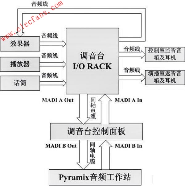
Figure 3 Signal flow of the audio system in the music studio.
As shown in Figure 3, the direction of the arrow represents the direction of transmission of the audio signal. The control panel of the DS-00 mixer is the center of the entire signal flow and is responsible for receiving and distributing signals from various devices in the system. There are two sets of MADI format signal interfaces on the mixer's control panel, MADI A and MADI B. The inputs and outputs of all devices in the system (except the Pyramix audio workstation) are connected to the corresponding signal format (analog or AES/EBU) interface on the I/O RACK of the mixer via the audio cable (XLR connector). . The I/O RACK communicates with the console's control panel in MADI format and is connected to the MADI LINKS A IN/OUT connector on the back of the control panel via two coaxial cables from the BNC connector. The Pyramix audio workstation and control panel also use the MADI format to transmit signals, and the coaxial cable from the two BNC connectors connects to the MADILINKS B IN/OUT connector on the back of the control panel.
2.1 Using a dedicated word clock signal generator as the system synchronization host
A high-precision digital clock generator LUCID SSG192 is installed in this digital audio system, as shown in Figure 4. It is suitable for most digital audio systems. It has an intuitive and convenient control panel. It occupies only a single rack space and can stably output a word clock signal with a sampling frequency between 32 and 192 kHz for a long time.
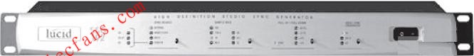
Figure 4 dedicated word clock signal generator LUCID SSG192.
As the synchronization host of the digital audio system, LUCID SSG192 generates the required word clock signal and transmits the signal to the signal distribution amplifier LUCID CLK×6 through the coaxial cable. There are 6 interfaces on the body of LUCIDCLK×6 that can output word clock signals. The word clock signals can be distributed to digital devices such as DS-00 mixer, Pyramix audio workstation, TC SYSTEM-6000 amplifier, DAT machine.
In practice, you need to select the desired sampling frequency on the control panel of the LUCID SSG192, and then set it in the menu of each digital audio device that needs to receive the word clock signal, and select their synchronization mode with the external word clock. Signal synchronization. After the word clock signal is directly input into the dedicated interface of the word clock signal of each device through the coaxial cable, each device will adjust its sampling frequency according to the sampling frequency of the word clock signal, and finally achieve synchronization with the LUCID SSG192, at this time in the system. The word clock signal transmission structure is a standard star structure, see Figure 5.

Figure 5 uses a dedicated word clock signal generator as the system synchronization master.
2.2 Using Pyramix Digital Audio Workstation as System Synchronization Host
In general, when there is a dedicated word clock signal generator in the system, it is recommended to use a dedicated word clock signal generator as the synchronization host of the system, because the word clock signal generated by the dedicated word clock signal generator is more stable. . When there is no dedicated word clock signal generator or word clock signal generator in the system, the digital mixer or digital audio workstation is usually used as the synchronization host of the system. The following describes how to use a Pyramix audio workstation as the synchronization host for your system.
First, you need to select its synchronization mode to synchronize with the internal clock in the menu of the Pyramix audio workstation. Next, select the source of the word clock signal for each device according to the signal format transmitted in the system. For example, the MADI format is used to transmit signals between the DS-00 mixer and the Pyramix audio workstation, so you can select the MADI option in the DS-00's sync setup menu and select a MADI channel that outputs signals from Pyramix to DS-00. The signal transmitted in this channel is used as the source for reading the word clock signal. At this time, the DS-00 reads the sync flag sent according to the MADI format from the coaxial cable that transmits signals from Pyramix to DS-00, and converts it into a word clock signal to adjust its own sampling frequency. The TC SYSTEM-6000 amplifier is not directly connected to the Pyramix audio workstation. Its input/output interface is connected to the mixer's I/O RACK via an audio cable, and AES/ is used between the mixer's I/ORACK. The EBU format transmits signals, so you need to select the AES/EBU option in the Synchronization Settings menu of the SYSTEM-6000 effect, and select an I/O RACK from the mixer to the AES/EBU channel of the SYSTEM-6000 input signal. The signal transmitted in this channel is used as the source for reading the word clock signal. At this point, due to the synchronization between the DS-00 mixer and the Pyramix audio workstation, the DS-00 mixer and the Pyramix audio workstation use the same sampling frequency in operation, in which case the SYSTEM-6000 is used from DS- 00 The clock information in the audio signal of the mixer adjusts its sampling frequency so that the sampling frequency of the SYSTEM-6000 and Pyramix audio workstations is actually the same. At this time, the word clock signal transmission direction in the system is consistent with the transmission direction of the audio signal, as shown in FIG. 6.

Figure 6 uses the Pyramix digital audio workstation as the system synchronization host.
3 Conclusion
The word clock synchronization method in digital audio systems is a more complicated problem. Today, with the rapid development of radio and television technology, the increasing use of digital audio equipment, and the increasing complexity of digital audio systems, the author believes that it is necessary to continue to conduct more in-depth research on this issue. In addition to the examples presented in this article, there are many ways to set the digital audio system to the word clock synchronization state in daily work. As long as the basic principles of the word clock signal synchronization method are mastered, the synchronization of the digital audio system can be achieved under any circumstances.
MOSO dimmable LED Driver is designed for various types of exterior or industrial LED lighting, including LED roadway lighting, LED street lighting, LED flood lighting, LED highbay lighting, LED high mast lighting, LED architecture lighting, etc. The driver is compliant to all 0~10V and PWM dimming controllers, dimming systems, and smart control systems.
All dimmable LED Drivers comes with compact size and IP67 protection. So the same driver can be used for independent or built-in a waterproof power supply chamber. There is no limitation of the IP rating of the luminaire housing.


The ProgrDimmable LED Driver operates in constant current model. There are two types dimmable LED drivers available in MOSO: 1) Programmable Dimmable LED Driver, or constant current dimmable LED driver.
A programmable dimmable LED driver can be monitored by an infrared-based programming device, to deliver different output current and voltage values to LED modules. With one driver, you can use it for different light fixture designs. The fully programmed drivers offer all dimming options (0-10V/PWM/Timing
control/DALI) and a wide range of output current in a single driver, which
deliver maximum flexibility with customized operating settings and intelligent
control options for lighting manufacturers. The Programmable dimmable LED drivers obtained many global safety certifications,
including UL, CE, TUV, ENEC, CB, SAA, BIS, KC, etc, they are compatible with the safety regulations
in different countries.
A constant current dimmable LED driver will only deliver fixed output current, you are not able to change the Iout like a programmable driver. The driver is competible with 0-10V / PWM / DALI dimming prootcols.
The compact metal case and high efficiency enables the power supply to operating with high reliability, and extending product lifetime to at least 50,000 hours. Overall protection is provided against lightening surge, output over voltage, short circuit, and over temperature, to ensure low failure rate.
MOSO grants the product with 5 years global warranty. Customer can refer to Warranty policy, find the closest MOSO distributors or sales representatives, to get a local replacement in case of any failure.
Dimmable LED Driver
Dimmable LED Driver,Dimmable LED Lighting Driver,Dimmable Slim LED Driver,Dimmable Tunnel Light LED Driver
Moso Electronics , https://www.mosoleddriver.com