Application of NI Software and Hardware Platform in Automobile ECU Development and Testing
introduction
This article refers to the address: http://
In today's automotive industry, regulations impose increasingly stringent requirements on safety, power, comfort, emissions, etc., and these properties are greatly affected by ECU performance and quality. Therefore, in the car, the number of ECUs continues to rise, and its functions are also constantly enhanced. In a car, a single ECU system and a plurality of ECU interconnection systems, such as an airbag ECU, and an latter such as an engine management system (EMS) ECU. EMS involves thousands of parameters and multiple electronic devices, and data sharing and transfer between these parameters requires interconnecting various electronic devices through different car buses to form an in-vehicle network and perform complex intelligent control and fault diagnosis. The complexity and functionality of ECUs continue to increase. To ensure the quality of the final product, automated testing is required to reduce human error from definition, analysis, design to implementation of different product cycles. In addition, there are challenges in how to bring products to market at the most economical cost in the shortest development cycle.
Controller develops "V" mode
After years of exploration, the industry generally uses computer-based controller development "V
"Mode, as shown in Figure 1. This mode can greatly reduce the iterative process and shorten the development cycle to save costs. In addition to the application of automotive ECU development, this mode has also been successfully applied to aviation, defense, "white" "Home appliances, medical equipment, industrial process control and other fields. The following is a brief description of the sequence of the corresponding steps in the horizontal direction of the "V" pattern.
System definition: According to the design requirements of the control system, complete the design specifications, such as control algorithms and control object parameters. It is often necessary to use previous design experience and test data for reference.
Design and simulation: According to the definition of the control system, the whole system is realized in the computer software environment, that is, the control logic of the controller and the control object environment are modeled and simulated to help the designer to quickly make system indicators and errors in advance. Evaluation. The simulation tools are mainly NI LabVIEW, The MathWorks, Inc. Simulink®, MATRIXx and so on. LabVIEW allows designers to model and dynamically simulate control systems in a graphical environment with the provided control simulation modules, as well as integrate models and code developed by third-party software, including The MathWorks, Inc. Simulink®, MSC CarSim, Even C code. MATRXx provides a complete set of system design simulation tools, especially for developing and managing large, complex models.
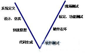
Figure 1 Controller development "V" mode diagram
Rapid Prototyping: Here, the concept of Rapid Control Prototype (Rapid Prototype) is distinguished from the rapid prototyping technology that automatically builds physical models based on CAD data in machine building. Because software simulation can't fully reflect the actual dynamic environment, you need to develop a controller hardware prototype to verify the algorithm in the real environment, that is, download the controller model to a real-time hardware platform and connect to the sensor in the real environment through I/O. , actuators and tests, the process is rapid prototyping, also often referred to as software in the ring. The real-time hardware platform was chosen for the timeliness, certainty and stability of the simulation.
Code Generation and Software Testing: After the controller model is validated by the rapid prototyping process, the model automatically or manually generates C code or other supported types of code and downloads it to the ECU's microcontroller. Test the generated target code.
Hardware in the loop: Hardware in the loop refers to the ECU that has downloaded the target code is connected to the previously established environment model (hardware-in-the-loop simulator) through I/O, and tests the ECU in various working conditions. Functionality and stability. The hardware-in-the-loop is a closed-loop test system that can perform dynamic simulations repeatedly; it can simulate road tests in summer and winter in the laboratory, eliminating the need for real test environment components, saving test costs; enabling critical condition testing and simulating extremes Conditions such as engine water temperature and oil temperature, ABS test speed and road adhesion coefficient, there is no actual risk; software (model), hardware (fault input module) can be used to simulate open circuit, short to ground, short between ECU pins Wait for errors, as well as analog sensor and actuator errors.
System calibration and testing: After completing the critical hardware-in-the-loop, connect the modified controller to the real I/O environment, and perform bench tests, road tests, and finally production.
The above controller development "V" mode conforms to the international automotive industry standard (ASAM/ASAP) and has been successful in many famous automotive electronics manufacturers. Rapid prototyping and hardware-in-the-loop are important aspects of controller development. Currently, solutions for these two links are generally faced with high cost. NI provides different, low-cost solutions for rapid prototyping and hardware-in-the-loop testing based on the complexity of the control system and the number of I/Os. For example, for an ECU with a relatively simple control algorithm and a relatively small number of I/Os, the CompactRIO platform can be selected for ECU rapid prototyping and hardware-in-the-loop testing; for more complex powertrain systems and active suspension systems, PXI real-time system platform is available. All of the above platforms have the characteristics of short development time, versatility, scalability, and low cost; and have been widely used at home and abroad, such as MicroNova, Wineman Technology, KGC, Averna, KPIT Cummins, etc., which have successfully provided OEMs. Solution; In China, such as Shanghai Volkswagen, a vehicle with multiple ECU hardware-in-the-loop tests is implemented under the NI PXI platform.
Here are two examples to illustrate the application of NI hardware and software platforms in controller rapid prototyping and hardware-in-the-loop.
Application example 1: Rapid prototype test of Yamaha motorcycle control system
Drivven, USA, is responsible for developing a prototype engine control system for the Yamaha YZF-R6 motorcycle. Project requirements: millisecond-level controller model cycle time; subtle fuel injection and ignition timing; and consider factors such as limited space for motorcycles and power supply to equipment.
After market research, Drivven finally chose the NI CompactRIO embedded system platform. The platform includes a real-time embedded controller, a chassis with built-in FPGA chips, and a built-in signal conditioning module. The entire system features a small, rugged, 9-35V DC power supply for complex test environments and limited test space. The FPGA chip is the core of the CompactRIO architecture, but the designer can use the LabVIEW FPGA module to develop custom FPGA logic code and download it graphically on the WINDOWS operating system without hardware description language and related expertise. The platform is an open platform that can be used with both off-the-shelf modules for different signal types and custom modules. Drivven develops according to project needs
Modular mixing module, fuel injection module, oxygen sensor module, variable reluctance and Hall module.
Through the LabVIEW real-time module programming, the combination of the speed density method and the throttle opening speed method commonly used in high performance racing cars is realized. The velocity density method is to calculate the intake air volume of each cylinder by using the engine speed and the intake air density. The system drives the injector to provide the required amount of oil to meet the theoretical air-fuel ratio requirements under various throttle states and at the throttle. The maximum torque demand in the open case is applied to low speed and low load conditions. The throttle opening speed method refers to finding the air quality experience value on a two-dimensional chart based on the two parameter values.
The CompactRIO prototype platform was placed on the motorcycle for testing. The system and program interface are shown in Figure 2 and Figure 3. The test results show that the engine speed can be as high as 15500RPM; the fuel injection and ignition timing can be well realized. At the same time, the real-time controller can record parameters such as intake air pressure and temperature, atmospheric pressure, cooling water temperature, throttle position, initial injection angle, and ignition advance angle during the test. Carroll G. Dase, president of Drivven, said: "Compared to similar projects in the past, the use of the CompactRIO platform has reduced the workload of the past two people from $500,000 a year to three-months and costs only $15,000. â€
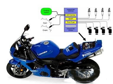
Figure 2 Engine Controller Hardware Prototype
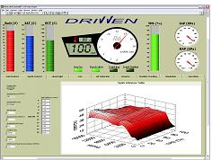
Figure 3 engine prototype host computer test interface
Application example 2: MicroNova engine hardware in-loop test
MicroNova, Germany, is faced with developing a compact, high-precision board for hardware-in-the-loop testing of automotive engine management systems in a short period of time, requiring the ability to simulate a complete test environment for 2-cylinder, 4-cylinder, 6-cylinder and 12-cylinder test environments.
Based on an understanding of the modularity and flexibility of the PXI platform, MicroNova chose the NI PXI platform, which includes the PXI-8196 real-time embedded controller, the PXI-7831 FPGA board, the PXI-6723 analog output board, and the PXI CAN module. Among them, PXI-7831 is a standard board that can provide analog input and output, digital input and output, PWM generation and measurement, and can realize non-standard signals such as crankshaft, camshaft, knocking and ignition through LabVIEW FPGA programming. The LabVIEW Simulation Interface Toolkit integrates the existing simulator model developed in the Simulink environment, and cooperates with the engine module provided by TESIS DYNAware to build a virtual test environment and run it in the PXI real-time controller. MicroNova has developed a signal conditioning module that modulates signal size, I/U, U/I, U/R, etc. to meet a similar ECU current requirement of several μA in sleep mode and up to 50 A in operating mode. . In addition, the system includes the Magneti Marelli ECU, fault input modules and real load.
The software architecture of the entire hardware-in-the-loop test system is shown in Figure 4. It consists of three parts: FPGA target, real-time system and host computer. The host computer is the user interface and the automatic test management program. The system is characterized by miniaturization, high precision, short development time and low cost. Not only can you directly use existing models, interface boards, etc.; you can also replace or expand modules according to system requirements; on-board FPGAs facilitate flexible and repeatable configuration, but do not require complex software and hardware knowledge; Numerous I/Os are synchronized at different bus speeds.
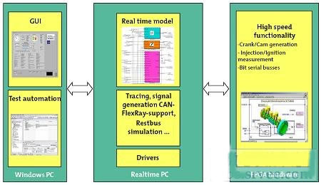
Figure 4 MicroNova engine hardware in-loop test software architecture
The platform has been successfully used as a hardware-in-the-loop simulator for a 12-cylinder direct injection engine from BMW; it can also be used in other different series of engines, such as V-12 with variable valve actuation, adjustable camshaft control, direct injection technology. 6-cylinder in-line engine; 4-cylinder in-line common rail diesel engine with turbocharged, air-cooled; V-2 engine for intake pipe injection of motorcycles, 2 knock sensors and double throttle.
to sum up:
At present, the "V" mode of controller development based on PC technology has become an effective method for the development of automotive ECU. For the two key aspects of rapid prototyping and hardware-in-the-loop, the designer can select the corresponding CompactRIO platform or PXI platform according to the ECU I/O quantity and the complexity of the control logic, and the whole system is implemented under the graphical design tool LabVIEW. No complicated hardware and software knowledge is required; all have the characteristics of low cost, short development time, scalability, and versatility.
Function: The Led Head Lamp has 1-5 modes;
Feature: The LED Head Lamp usually high power and super bright;
Trait: The products are waterproof, shockproof and tactical;
Method of application: Simple on/off push button operation, or motion sensor;
Range of application: The LED Head Lamp for emergency events, camping, outdoor activities;
Adervantages: Our products are saled with factory price, and the quality can guarantee, lastly we provide warranty for 1 year.
LED Head Lamp
Led Head Lamp,Headlamp Torch,Led Headlamp,Led Head Torch
Ningbo Henglang Import & Export Co.,Ltd , https://www.odistarflashlight.com