The use of scanner console
The use of scanner console
Various manufacturers of scanners have scanner control consoles for scanners of their own brands. These consoles are difficult to control scanners of other brands. Although scanners accept DMX512 international standard signals, they cannot achieve the general purpose.
PULSAR108 console is a computer console produced by British sand company, it can output 0-10V signal, RS232 signal and DMX512 signal, output channel 108. It can memorize 216 scenes of SCENE, 54 scenes of running lights, and 6 environment chases of CHASE ENVIRONMENT. The control board is equipped with a magnetic card recording interface, which can conveniently store lighting programs. The PULSAR108 control station can output 108 independent channels, and each channel can control a channel of a digital device that accepts DMX512 signals. In other words, no matter which brand of scanner or digital silicon box, as long as it accepts DMX512 signal, PULSAR108 console can control it. For example, there is a 14-channel scanner, which occupies 14 channels on the console. The 14 channels depend on the address code of the scanner. Find the channel with the same address code on the console From this channel, the 14 backward channels are all channels of this scanner. Because PULSAR108 only has 108 channels, the address code of the scanner cannot exceed this range. It can be seen from the above that PULSAR108 realizes the universality of standard signals.
Next, briefly understand the programming of the PULSAR108 console. Let's first look at its programming steps. First, remember the lighting effects as a SCENE scene. You can divide the required lighting effects into several scenes and remember them separately, and then save the scenes in sequence to the CHASE scene running lights. This will complete a simple The lighting program, consisting of light path, scene and scene running lights, can constitute 48 ENVIRONMENT environments, and 6 environment running lights can be connected to any 48 environments as running light programs. Now make a simple CHASE scene running light, memorize the required SCENE scene, make the scanner into the desired effect, press the SAVE OUTPUT SCENEPAD memory scene key, select a page in the scene page S1-S3, from 18 KRYBOARD Select a key in the PADS numeric keyboard as the position of this light effect. This completes the memory of a scene. In the same way, all the required light effects are memorized as a scene. Once you have a scene, you can memorize the CHASE scene running lights, press the PROGRAM CHASE SEQUENCE PAD memory scene running light button, select any page of the scene running light page C1-C3, select a position from the 18 numeric keypad, and find the storage light On the scene page of the effect, press the number keys that store the lighting effect position in sequence. Now that the scene has been saved in the scene running light, finally press the PROGRAM CHASE SEQUENCE PAD memory scene running light button to end editing the scene running light. When the running light program is called out, you can see that the lighting effects will change in the order of arrangement. Use the SPEED speed fader and SLOPE cadence time fader to adjust the speed of the running lights and the smoothness between steps. The PULSAR108 console also has a four-digit password to prevent non-professional operations. Once the program is lost, the light program can also be copied to the console through the magnetic card, but its output channel is too few and there are only 108 channels, and 14 channels of scanners can control 7 units. Many large-scale performances often use hundreds of computer lights at one time, so more output channels, more convenient use, and more powerful computer consoles are needed.
A computerized console called AZURE2000 (Azure 2000) from the British Afri company can output four standard DMX512 signals, with up to 2048 output channels, which can control 200 scanners and 200 dimming channels. There are 10 replay faders and 40 replay buttons, which can memorize 500 scenes or running lights, and the memory of the running light steps is not controlled by the memory limit of the console. The console can run 20 scenes or running lights at the same time. It is equipped with a 3.5-inch floppy disk drive to store or load lighting programs, as well as software installation and console upgrade operations. The console is equipped with a VGA interface for external display, and the display can be used to view the current operation status, various output parameter system menus and so on.
First understand the operation interface and display interface of AZURE2000. The operation interface is divided into blue and gray areas. The blue area is provided with the system menu key area. This area is provided with a numeric keypad and 7 [AG] buttons corresponding to the system menu. The device selection area is 1- The 20 buttons can select the corresponding dimming channel or scanner. The control mode area can make the console enter different operation modes. The scanner function selection area can choose to switch the scanner function. The gray area is mainly the replay button and replay fader, running light control and environmental control, etc. The specific content of the menu can be seen from the lower left of the display. The content controlled by the two data wheels A and B and the running status of the running lights are displayed at the lower right of the display. The [ON SCREEN] key in different areas can expand different display interfaces, such as: light path output, scene and running light page, etc. You can get operation prompts in the information window at the bottom of the display.
AZURE2000 can control all scanners that accept DMX512 digital signals. The controller must be set before controlling the scanner. Generally divided into two methods. First, set the console first, and then set the address code for the scanner according to the settings of the console; Second, first set the address code of the scanner, and then set the console according to the address code of the scanner. The program files of the relevant scanners are required when setting up the console. General scanners can be found in the lamp library that comes with AZURE2000. If there is no model that requires a scanner, you can download the program file for the scanner online.
Before setting, it is best to do a machine cleaning operation, select SUPERVISOR management mode in the console mode selection area, select WIPEAL machine cleaning in the system menu, press the "F" button in the small keyboard area, the system will prompt whether to perform machine cleaning Operation, and then press the "F" button to complete the operation.
After entering the PROGRAM editing mode of the console, the console can be set. Select the PATCH setting button in the blue area. The DIMMER and FIXTURE buttons on the side flash at the same time, prompting you to set the dimming channel or scanner channel, and the display will The current DMX link output status is displayed, and the operation options are also displayed in the menu area in the lower left corner of the display. Here you can also select the DIMMER OR FIXTURE channel, and you can also select the DMX link output. There are four ABCDs to choose from. It should be noted that when the device is connected, it must correspond to the selected link. Select the FIXTURE control button, the console will read the lamp library data in the floppy drive, the display will show all the scanner brands, select the corresponding brand and press ENTER to enter, then all models of this brand scanner will be displayed, select Press the ENTER control button for the correct model, the console will read YES or NO in the menu area of ​​the display after reading the scanner file, press the A button (YES), the display will show the DMX link output status again , The information window at the bottom of the display screen will prompt you to set the scanner in the position of the DMX link, enter the address code of the scanner programmed in advance using the keypad, or use the default value. Select a preset page in the device selection area and select a position from 20 preset positions. At this time, you will see that the DMX link output has the same number of DMX output channels as the scanner channels. Now you have completed the setting of one scanner. If you want to set multiple scanners of the same model, press and hold the first and last buttons of the preset position at the same time to set the selected area as the scanner of this model. , The same method can be set to other scanners. Finally press EXIT to exit the setting operation.
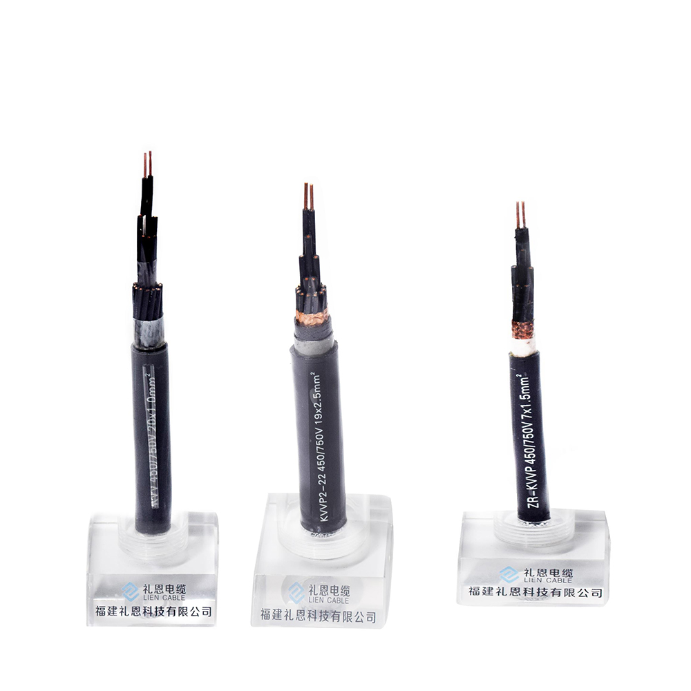
Control cable, insulated by PVC,XLPO/XLPE or PTFE material, is applicable for controlling and protecting circuits of rated voltage up to and including 450/750 V, used in enterprises of industrial and mining and department of energy source and transportation. It belongs to electrical equipments use cable which transmits electrical power from power system to various electrical equipments and tools.
Product specification
l Conductor type: stranded 99.95% OFC(oxygen free copper)
l Material :environmental friendly, fire resistant, flame retardant, low smoke halogen free, heat resistant
l Control cable color: black or other customized color
l Packing: carton packing, pallet packing, wooden steel drum or other packing method as requirements.
Three Main Type of our Control Cable
l PVC Insulated sheathed control cable
l Fire resistant control cable(PTFE)
l Radiation XLPO insulated control cable


Using features
*Rated power-frequency rated voltage U0/U is 450/750V
*Max. permissible continuous operating temperature of conductor:
l PVC Insulation type: 0℃
l XLPE Insulation type: 90℃
l PTFE Insulation type: 40℃~200℃
l XLPO Insulation type: 125℃
*The ambient temperature under installation should not be lower than 0℃, if the ambient temperature is below 0℃,the cable should be preheated.
Standard
This cable is manufactured according to GB/T9330-2008 standard. It can also be manufactured according to other standards upon request.
Application
Industrial and mining enterprises: iron and steel, coal manufacturing, etc
Modern high-rise building
Connecting line of electrical instruments and automation devices
For laying indoors, in trenches and in ducts, the cable should be shielded and for fixed installation.
Notes for installation
1. Don`t directly expose to the sunlight or superheat.
2. Don`t forget to check dry and wet level for installations in trenches regularly.
We can manufacture control cables as customer`s requirements. Welcome to contact us for more details about products and price. If later you want to visit our factory to get close to our production line, please also feel free to get in touch with us.
Control Cable
Control Cable,PVC Control Cable,Multicore Control Cable,Throttle Control Cable
Smartell Technology Co.,Ltd , http://www.liencable.com