ADuC841-based data acquisition and wireless transceiver system
ADuC841-based data acquisition and wireless transceiver system
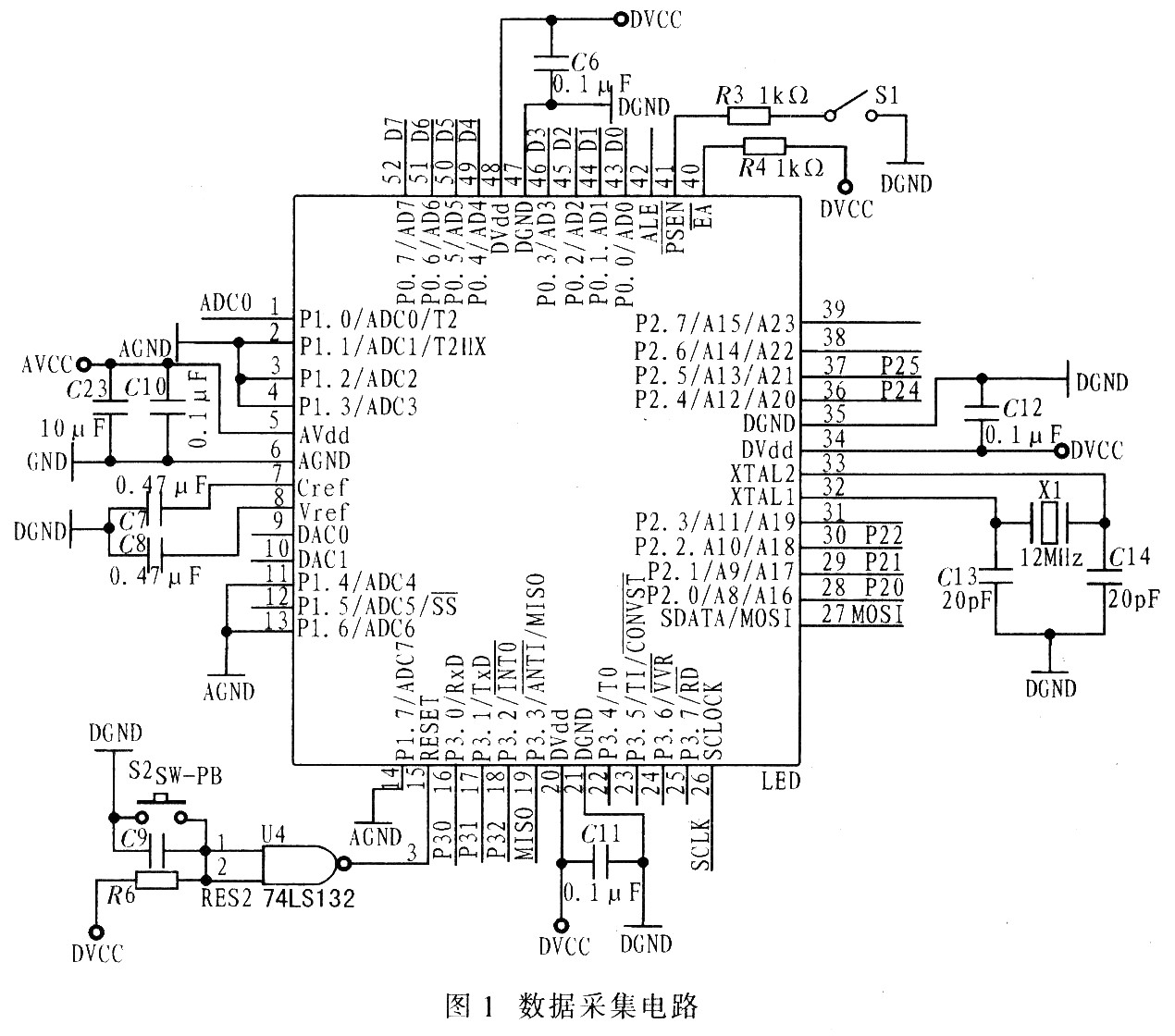
1 Introduction Traditional measurement and control scenes send and receive data by wire. But cable transmission is not suitable under some special conditions, not only high cost, but also low measurement accuracy. Therefore, a design scheme of data acquisition and wireless transceiver system based on ADuC841 is proposed here. 2 Design of data acquisition part The ADuC841 acquisition system consists of analog multiplexer, temperature sensor, sample and hold circuit, 12-bit successive approximation A / D converter, and +2.5 V reference voltage. The effective range of the analog input voltage of the ADuC841 is related to the reference voltage. When the ADuC841 uses an internal reference voltage, its effective input range is 0 to +2.5 V. ADuC841 can work in the working temperature range of -40 ℃ ~ + 85 ℃, with 3 V and 5 V power supply modes. The A / D converter module contains an 8-channel 12-bit, single-supply A / D converter with a sampling frequency of up to 420 kS / s (2.38 μs). In applications requiring high-speed data acquisition, to prevent A The sampling result of the / D converter is lost, and the DMA mode can be used. The ADuC841 microcontroller A / D converter has three control registers: ADCCON1 ~ ADC-CON3, and its operation mode, conversion and acquisition time depend entirely on the settings of these three control registers. The control register ADCCON1 controls the A / D converter conversion and acquisition time, hardware conversion mode and power-down mode: the control register ADCCON2 sets the A / D converter channel and conversion mode; and the control register ADCCON3 controls various calibration modes and instructions A / D D converter is busy. Figure 1 shows the data acquisition circuit.
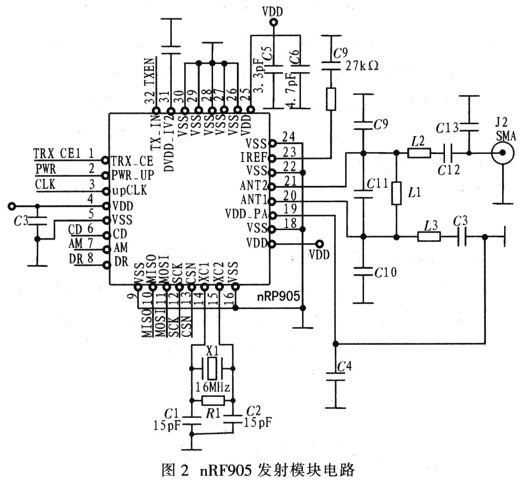
3 Design of wireless transceiver part The wireless transceiver part adopts nRF905 monolithic RF transceiver, it can work at 433/868/915 MHz 3: ISM (Industrial, Scientific and Medical) channels, internally integrated frequency modulator, with demodulation Receiver, power amplifier, crystal oscillator and regulator. Main features of nRF905: The conversion time between channels is less than 650 μs. The working voltage is 1.9 ~ 3.6 V, 32-pin QFN package. The preamble and CRC check code are automatically generated and can be easily configured through the SPI interface. The connection of peripheral devices is simple, no external SAW filter is needed. nRF905 has ShockBurst TM to send ShockBurst RM to receive two working modes and two power-saving modes of power down and SPI programming mode, STANDBY and SPI programming mode. The working mode of nRF905 is determined by the three pin settings TRX_CE, TX_IN, PWR_UP. Figure 2 shows the nRF905 transmitter module circuit.
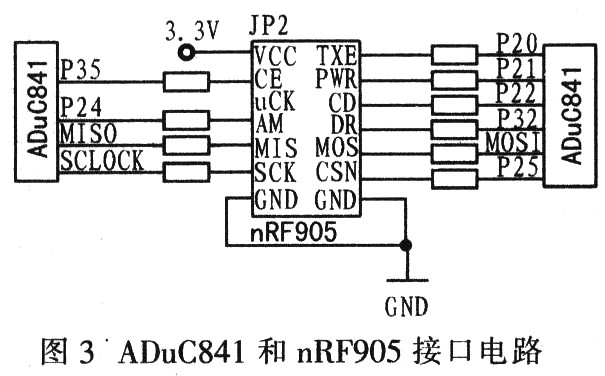
ADuC841 controls the transmission of nRF905 through its internal integrated SPI interface. The interface circuit is shown in Figure 3. The SPI serial port can simultaneously send and receive 8-bit data, that is, duplex working mode. The SPI interface has 4 lines: serial clock line (SCLOCK), master input slave output data line (MISO), master output slave input data line (MOSI), and low-level slave selection (SS).
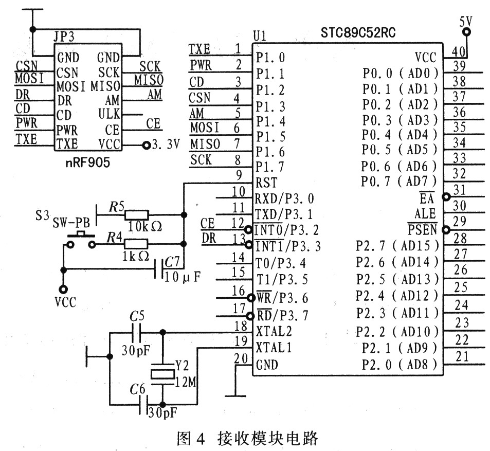
The receiving module circuit adopts STC89C52 single-chip microcomputer to control the receiving of nRF905, simulate SPI communication, and upload the received data to the PC for display through the serial port. Choose the lower cost STE89C52 here, which can reduce the overall system cost. Figure 4 shows the receiver module circuit. The data acquisition and wireless transceiver system uses the acquisition function of the ADuC841 microcontroller to detect analog signals, and uses the SPI interface of the microcontroller to communicate with the nRF905. Realize the wireless transmission and reception of data, thus forming a practical data collection system.
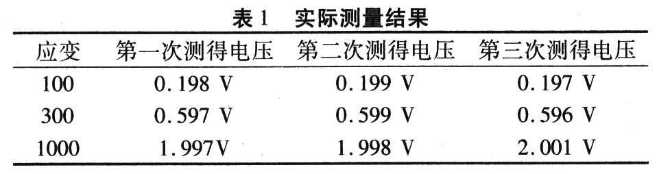
4 Test results The system design was tested in the laboratory. One of the strains corresponds to 0.002 mV, and the reference voltage of the A / D converter is 2.5 V. In the test, the voltage values ​​corresponding to different microstrains of 100, 300, and 1 000 are selected, and then wireless transmission is performed. The actual measurement results are shown in Table 1. From Table 1, it can be seen that the three measured values ​​are within the allowable error range, and the transmission and reception of wireless data are completely the same, which meets the actual engineering application standards.
5 Conclusion Data collection is widely used in engineering practice, and there are many types of designs. The data acquisition system adopts ADuC841 single-chip microcomputer and nRF905 monolithic RF transceiver design to achieve data acquisition and real-time transmission. The entire system is simple in design, stable in data transmission, and convenient for long-distance measurement.
low voltage electric appliances is a kind of equipment that can manually or automatically connect and disconnect the circuit,according to the requirements of the outside . In order to realize the circuit or non-electric object switching, control, protection, detection, transformation and adjustment. Korlen electrical appliances can provide the perfect(quality and service) products with good safety: AC Contactor,Thermal Relay,Manual Motor Startor etc.
AC contactor:
|
pe |
KNC1-09 |
KNC1-12 |
KNC1-18 |
KNC1-25 |
KNC1-32 |
KNC1-40 |
KNC1-50 |
KNC1-65 |
KNC1-80 |
KNC1-95 |
||
|
Pick-up voltage |
(0.85~ |
(0.85~ |
(0.85~ |
(0.85~ |
(0.85~ |
(0.85~ |
(0.85~ |
(0.85 |
(0.85~ |
(0.85~ |
||
|
Release voltage |
(0.2~ |
(0.2~ |
(0.2~ |
(0.2~ |
(0.2~ |
(0.2~ |
(0.2~ |
(0.2~ |
(0.2~ |
(0.2~ |
||
|
Coil power |
50Hz |
Pick-up(VA) |
70 |
70 |
110 |
110 |
110 |
200 |
200 |
200 |
200 |
200 |
|
Holding(VA) |
8 |
8 |
11 |
11 |
11 |
20 |
20 |
20 |
20 |
20 |
||
|
Pick-up(VA) |
80 |
80 |
115 |
115 |
115 |
200 |
200 |
200 |
200 |
200 |
||
|
Holding(VA) |
8 |
8 |
11 |
11 |
11 |
20 |
20 |
20 |
20 |
20 |
||
|
Power |
1.8~2.7 |
1.8~2.7 |
3~4 |
3~4 |
3~4 |
6~10 |
6~10 |
6~10 |
6~10 |
6~ |
||

If you have any questions,please contact with us directly,welcome to visit our factory.For inquly.please send mail directly to us.
Low Voltage Transformer,Low Voltage Motors,Relay & Contactor
Wenzhou Korlen Electric Appliances Co., Ltd. , https://www.korlenelectric.com