RF and wireless chip test basic knowledge analysis
This article describes the testing of RF/wireless chips. The RF/wireless system includes a transmitter and receiver for transmitting and receiving signals, respectively. Let's first introduce the basic test of the transmitter, and then introduce the basic test of the receiver.
Transmitter test basisAs shown in Figure 1, the digital communication system transmitter consists of the following components:
· CODEC (encoder / decoder)
· Symbol encoding
· Baseband Filter (FIR)
· IQ modulation
· Upconverter (Upconverter)
· Power amplifier
The CODEC uses a digital signal processing method (DSP) to encode the sound signal for data compression. It also performs other functions, including convolutional coding and interleaving coding. The convolutional code copies each input bit, uses these redundant bits for error checking and increases the coding gain. Interleaved coding can make the code bit error distribution more uniform, which makes the error check more efficient.
Symbol encoding converts data and information into I/Q signals and defines the symbols as a specific modulation format. The baseband filtering and modulation shaping filters increase the bandwidth efficiency by trimming the steep edges of the I/Q modulated signal.
The IQ modulator makes the I/Q signals orthogonal to each other (integral sense) so they do not interfere with each other. The output of the IQ modulator is a combination of IQ signals, which is a single IF signal. The intermediate frequency signal is converted into a radio frequency signal by an up-converter, and then amplified by being transmitted.
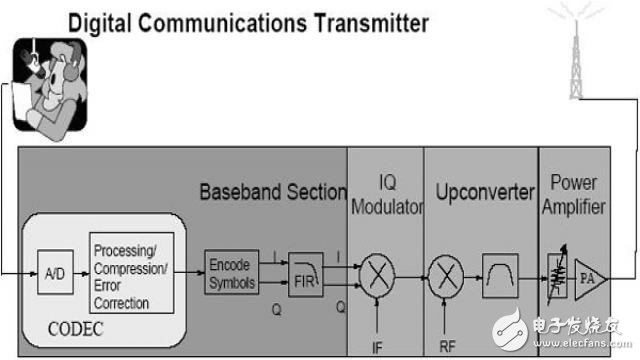
Figure 1. Simple block diagram of a universal digital communication system transmitter
Advanced digital signal processing and dedicated application chip technology increase the integration of digital systems. Now a single chip integrates most of the functions from ADC to IF modulated output. As a result, RF test points at the module and chip levels are much reduced, and test and fault analysis at the transmitter system and antenna ends becomes more important.
The main test content of the transmitterIn-channel test
In-channel testing uses time division multiplexing or code division multiplexing to test wireless digital circuits. Reuse refers to frequency or spatial multiplexing. In time division multiple access (TDMA) technology, a channel can be defined as a specific frequency band and time slot in a series of repetitive frames, while in code division multiple access (CDMA) technology, a channel is defined as a specific code segment and Frequency band. The terms intra-channel and out-of-channel refer to the frequency band (frequency channel) we are interested in, rather than the time slot or code segment of the channel within the frequency bandwidth.
The transmitter channel bandwidth is the first test that determines the spectral characteristics of the transmitter's transmitted signal. Through the shape and characteristics of the spectrum, many errors in the design can be found, and the error rate of the system symbol rate can be roughly estimated.
The carrier frequency test is used to test frequency errors that may cause channel interference in adjacent bands or affect receiver carrier recovery. In most modulation modes, the carrier frequency should be at the center of the spectrum. The center frequency can be determined by calculating the 3dB bandwidth.
The channel power test is used to test the average energy of the wanted signal over the frequency bandwidth. It is usually defined as the average of the useful signal energy over the signal frequency bandwidth, and the actual measurement method will vary with different standards. The wireless system must ensure that the energy consumed by each link is the least. There are two main purposes: one is to reduce the overall interference of the system, and the other is to extend the life of the portable system battery. Therefore, the output power must be strictly controlled. In CDMA systems, the total interference tolerance of the system also severely limits the power of each individual mobile unit in order to achieve maximum capacity. Accurate transmit power control is critical to system capacity, coverage and signal quality.
Occupied bandwidth is closely related to channel power and is defined as how much spectrum is covered by the percentage of power of a given total modulated signal.
Time testing is commonly used for burst signal testing in TDMA systems. These tests are mainly used to evaluate whether the carrier envelope can meet the expected requirements, including burst signal width, rise time, fall time, turn-on time, turn-off time, peak power, transmit power, turn-off power, and duty cycle. The time test can ensure that the interference between adjacent frequency channels and the interference when the signal is switched on or off is minimized.
Modulation quality testing typically involves accurate demodulation of the transmitted signal and comparison to an ideal mathematically computed transmitted or reference signal. Actual measurements will vary depending on the modulation method and the different standards.
Error Vector Magnitude (EVM) is the most widely used modulation quality parameter for digital communication systems. It samples the output signal at the output of the transmitter to obtain the trajectory of the actual signal. The output signal is usually demodulated to obtain a reference signal. The vector error is the difference between the ideal reference signal at a certain time and the actual measured signal, and is a complex number containing the amplitude component and the phase component. Typically, the EVM will use the largest symbol amplitude component or the square root of the average symbol power.
I/Q offsets (inherent offset origin offsets) are caused by the DC offset of the I/Q signal and may cause carrier feedback.
Phase and frequency error tests are used for equal amplitude modulation. By sampling the output signal of the transmitter and capturing the actual phase trajectory, an ideal reference phase trajectory is obtained after demodulation. The phase error is obtained by comparing the actual signal with the ideal reference signal and is expressed in the form of effective values ​​and peaks. Large phase errors indicate problems with the transmitter baseband or output amplifier, resulting in a decrease in signal sensitivity. The frequency error is the error of the carrier frequency. A stable small frequency error indicates that the carrier being used may have some problems. Unstable frequency errors can be caused by instability of the local oscillator, the use of improper filters, problems with the amplitude modulation phase modulation conversion of the amplifier, or the use of transmitter analog frequency modulators. There is a problem with the modulation index.
Out-of-channel test
Out-of-channel testing is the measurement of those bands outside the system frequency.
Off-channel testing is the sampling of distortion or interference in the system band, rather than testing the transmission frequency itself.
The adjacent channel power ratio (ACPR) test ensures that the transmitter is not interfered by adjacent or spaced channels. ACPR is the ratio of the average power of adjacent channels to the average power of the transmitted channel. Measurements are typically made between channels that are separated by multiple channels (between adjacent channels or spaced channels). When performing ACPR testing, it is important to consider the statistical nature of the transmitted signal, because even for the same transmitter, different signal statistics can result in different ACPR test results. For different standards, the test usually has different names and definitions.
Clutter signals are caused by different combinations of signals within the transmitter. The amplitude of such a signal in the system band must be less than the level specified by the standard to ensure that it has minimal interference with other communication systems.
Harmonics are signal distortions caused by the nonlinearity of the transmitter, and the frequencies of these signals are all integer multiples of the carrier frequency. Tests for out-of-channel clutter and harmonics are used to ensure that this channel has minimal interference to other communication systems.
Receiver basic test
The function of the receiver is basically the reverse process of the transmitter, so the test challenges they bring are also very similar. The receiver must successfully capture the RF signal under potentially disturbing conditions, so a front-end selection filter must be used to filter out or attenuate signals outside the system band received by the antenna. The low noise amplifier (LNA) amplifies the amplitude of the target signal, but at the same time ensures that the noise amplitude is increased as little as possible. The downconverter converts the RF signal to a lower frequency intermediate frequency signal by mixing with the local oscillator signal. The mixer's output signal then attenuates the unwanted frequency components produced by the mixer or adjacent channels through the IF filter.
The digital receiver (Figure 2) can be implemented with an I/Q demodulator or a sampled intermediate frequency IF. I/Q demodulation is implemented by analog hardware and is common in the design of digital RF receivers. Although this method is very popular, it has a potential problem: the gain on the I/Q path is less consistent, and the relative phase deviation is also large (greater than 90 degrees), which in turn leads to image rejection problems. Therefore, the I/Q demodulation method is mainly used for a single channel base station.
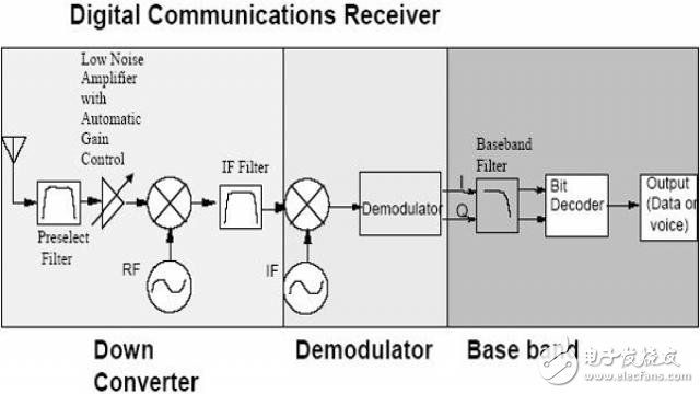
Figure 2. Typical digital communication receiver
Asia-Pacific generated the highest revenue in the market in 2017, and is expected to lead the global Lithium Iron Phosphate Battery market throughout the forecast period. The increasing demand for electric vehicles in the region is expected to drive the growth of Lithium Iron Phosphate batteries in this region. The growing use of Lithium Iron Phosphate batteries in renewable energy storage systems also accelerates the adoption. The increasing demand for consumer electronics from countries such as China, Japan, and India, along with stringent government regulations boost the Lithium Iron Phosphate Battery market growth.
The companies operating in the Lithium Iron Phosphate Battery market include Panasonic Corporation, Toshiba Corporation, Samsung SDI Co., Ltd, Toshiba Corporation, BYD Company Ltd., GS Yuasa Corporation, Valence Technology, Inc., A123 Systems, LLC., Formosa Energy & Material Technology, and Bharat Power Solutions. These companies launch new products and collaborate with other market leaders to innovate and launch new products to meet the increasing needs and requirements of consumers.
Portable Energy Storage System,Portable Energy Storage Market,Portable Power Storage,Portable Energy Storage
Shenzhen Sunbeam New Energy Co., Ltd , https://www.sunbeambattery.com