Performance Analysis of LVDS Serial-deserializer in Data Transmission of Twisted Pair Cable
The use of serial-deserializers can greatly reduce the wiring in short-range and broadband data communications. Similar applications include backplane interconnection for telecommunications and network equipment, intra-rack interconnection in 3G cellular phone base stations, and digital video interfaces Wait. The advantages of current mode, low voltage differential signaling (LVDS) are easy termination, low transmission power consumption, and low electromagnetic interference (EMI).
The main standard of LVDS, TIA / EIA-644-A, only specifies physical layer parameters such as signal level, and does not give the interconnection characteristics such as the correspondence between data rate and cable length. The LVDS standard provides users with only the basic compatibility specifications of LVDS signals. In high-speed applications, users must also understand the performance that can be achieved under the specified cable and transmission distance conditions.
This paper presents the laboratory test results and analyzes the bit error rate (BER) specifications of the MAX9205 / MAX9207 LVDS serializer and the MAX9206 / MAX9208 deserializer at different data rates and cable lengths. This article also explores BER related to jitter in the link eye diagram.
Maxim's MAX9205 / MAX9207 LVDS serializers and MAX9206 / MAX9208 LVDS deserializers can transmit data at high speed through serial point-to-point links with differential characteristic impedance of 100Ω, and the serial "payload" data rate of the MAX9205–MAX9206 (including synchronization codes) ) Is 160Mbps to 400Mbps; MAX9207–MAX9208 rate is 400Mbps to 600Mbps. The two groups of chips are pin compatible, but are optimized in different frequency ranges. This article provides the BER and eye diagrams at different transmission distances using unshielded cables (CAT-5E).
The BER test is the most direct and accurate way to measure the reliability of the transmission link. The digital communication link requires a very low bit error rate-one hundredth of a billion (BER is 10-12) or lower.
Performing BER testing requires high-quality signal generators and specific test equipment. BER testing requires hours or even days to transfer large amounts of data to achieve BER test requirements of 10-12 or lower, depending on the data transmission rate. Considering that the BER test is time-consuming, some fast measurement methods are usually used to predict the reliability of the transmission link, such as setting the jitter level that produces low BER. We tested the jitter specifications of the MAX9205–MAX9206 and MAX9207–MAX9208 links (Figure 3 It is marked as "marginal jitter" and is related to BER. BER test is usually used to verify the maximum value of jitter index in the data sheet. Figure 1 shows the configuration of establishing a point-to-point link with an LVDS serializer / deserializer.
The test device MAX9205 or MAX9207 LVDS serializer sends the LVDS signal. The serializer latches 10-bit parallel data on the rising edge of the parallel data clock (TCLK), adds the 2-bit synchronization code, and sends the serial data through the single LVDS output port. The parallel data clock range of the MAX9205 is 16MHz to 40MHz; the clock range of the MAX9207 is 40MHz to 60MHz. After adding the 2-bit synchronization code, the serial data bit rate is 12 × TCLK. The "payload" serial data rate (serial bit rate minus the 2-bit synchronization code) is 10 × TCLK. The functional block diagrams of MAX9205–MAX9207 and MAX9206–MAX9208 are shown in Figure 1.
Figure 1. Functional block diagram of serializer / deserializer
In the cable test setup (Figure 2), the serializer and deserializer of the No. 2 evaluation board convert the serial I / O of the Agilent 86130A BER tester into parallel I / O. Parallel data is sent to or read from the No. 1 cable test and evaluation board. The serial data sequence code output by the 86130A is 1200 bits long, of which 1000 bits are taken from the 210-1 pseudo-random binary sequence (PRBS), and every 10 bits of the PRBS code are inserted into the 01 synchronization code to add bits to the serializer. The deserializer on the No. 2 evaluation board removes the synchronization code and outputs PRBS parallel data to the No. 1 evaluation board's cable test serializer. The serial data sequence is continuously sent repeatedly, and the Agilent 81250 provides the required reference clock (TCLK is used for the serializer and REFCLK is used for the deserializer). The Ethernet cable 5E and AWG24 unshielded twisted pair (model 2133629H) produced by General Cable Inc. are used.
Figure 2. Cable test setup
We tested the BER at 5 ft, 15 ft, 30 ft, 60 ft, and 100 ft cable lengths respectively, and used Tektronix TDS784C oscilloscope and Tektronix P6247 1.0 GHz differential detector to understand the eye diagram jitter characteristics at the input end of the stringer. The delay time of the TCLK serializer reference clock provided by 81250 can be adjusted to meet the requirements of the serializer input setup time and hold time listed in the data sheet.
Test results The MAX9205–MAX9206 and MAX9207–MAX9208 serial-deserializer pairs were used in the test. The serial bit rate provided by the 86310A for the MAX9205–MAX9206 is 192Mbps to 480Mbps, and the bit rate provided for the MAX9207–MAX9208 is 480Mbps to 720Mbps.
In order to quantify the integrity of the eye signal, two parameters are defined: total jitter (tTJ) and critical jitter (tMJ), tTJ is the jitter time width tested when the differential voltage is 0 (0 differential voltage is the horizontal axis of the oscilloscope trace) , TMJ is the time interval between the jitter midpoint at zero differential voltage and the jitter midpoint corresponding to the 300mV peak differential voltage (Figure 3). One might expect the deserializer-differential input to switch at a differential voltage of 0V, but the more conservative approach is to assume that additional differential voltage is required to provide overdrive. The level conversion corresponding to tTJ occurs at a 0V differential voltage, while tMJ requires that the differential signal must reach 300mVP-P before converting the input level of the deserializer. This shows that using tMJ to detect signal integrity is more reliable. tUI (Figure 3) is defined as the duration (unit interval) of a one-bit serial code. The unit interval is the reference frequency period divided by 12.
The differential peak voltage is expressed by VP-P, which is twice the difference amplitude of the single-ended voltage at the test point, or VP-P = 2 × l (VOUT +)-(VOUT-) l. For example, if the high level obtained at the test point with respect to ground potential is: VOUT + = 1.35V, VOUT- = 1.10V; the low level obtained with respect to ground potential is: VOUT + = 1.10V, VOUT- = 1.35V, Then VP-P = 500mV. Because the test uses a differential probe (the test result is VOUT + minus VOUT-), the eye diagram shows the result of VP-P.
Figure 3. Definition of jitter parameters
Table 1 lists the maximum tMJ specified in the MAX9206 / MAX9208 deserializer data sheet. If tMJ is lower than or equal to the maximum value listed in the table, the deserializer can ensure data recovery.
Table 1. Maximum critical jitter
The test process is carried out under two conditions. The first test condition is: the serial test template runs at the highest rate allowed by the serial-deserializer pair for 1 hour at different cable lengths, and tests tTJ, tMJ and error Number of codes; The second test condition is: under the condition of maximum jitter (greater than the maximum value of tMJ in the data table), send serial test data for more than 10 hours (send code length greater than 1.73 × 1013 bits), test tTJ, tMJ and number of errors.
Table 2 and Table 3 are the test results of the MAX9205–MAX9206 and MAX9207–MAX9208 serial-deserializers under 5 to 60 feet of cable length. The bit rate is the serial signal rate, and the data rate is the "payload" serial data rate (data rate = (10/12) × bit rate).
Table 2. MAX9205–MAX9206 tTJ, tMJ, VP-P, and bit error rate (measurement time 1 hour)
* The measurement resolution of tTJ and tMJ is 10ps, and the measurement resolution of VP-P is 2mV.
Table 3. MAX9207–MAX9208 tTJ, tMJ, VP-P and bit error rate (measurement time 1 hour)
* The measurement resolution of tTJ and tMJ is 10ps, and the measurement resolution of VP-P is 2mV.
According to the test results, Figure 4 shows the eye diagram obtained by testing the MAX9208 deserializer after 30-foot and 60-foot cable transmission.
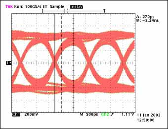
Figure 4a. The eye diagram of the MAX9207–MAX9208 after a 30-foot cable transmission, with a data rate of 720Mbps, tTJ = 220ps, tMJ = 270ps, and transmission of 2.592 × 1012 bits.
No error code, vertical scale: 200mV / Div, horizontal scale: 500ps / Div.
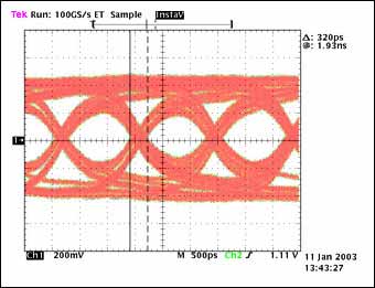
Figure 4b. The eye diagram of the MAX9207–MAX9208 after a 30-foot cable transmission, with a data rate of 720Mbps, tTJ = 320ps, tMJ = N / A, and a transmission of 2.592 × 1012 bits.
No error code, vertical scale: 200mV / Div, horizontal scale: 500ps / Div.
To determine the ability of the deserializer to recover data under signal degradation conditions (ie, the jitter margin is lower than the specified parameters in the data sheet), two sets of serial-deserializers were tested under a 100-foot cable. The test data has been sent continuously for more than 10 hours. Table 4 shows the jitter test results, voltage peaks, and bit errors. Figure 5 shows the eye diagram.
Table 4. MAX9205–MAX9206 and MAX9207–MAX9208 tTJ, tMJ, VP-P, and bit error rate
* The measurement resolution of tTJ and tMJ is 20ps, and the measurement resolution of VP-P is 2mV.
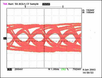
Figure 5a. Eye diagram after transmission through a 100-foot cable, data rate: 480Mbps, tTJ = 660ps, tMJ = N / A, transmission 1.73 × 1013 bits without errors, vertical scale: 200mV / Div, horizontal scale: 1ns / Div
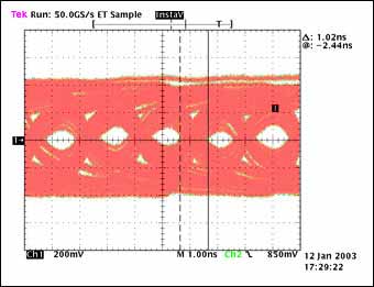
Figure 5b. Eye diagram after transmission through a 100-foot cable, data rate: 520Mbps, tTJ = 1020ps, tMJ = N / A, transmission 1.87 × 1013 bits without errors, vertical scale: 200mV / Div, horizontal scale: 1ns / Div.
There is no error code recorded in all test results. The signal amplitude after a 100-foot cable transmission at a bit rate of 520Mbps is 110mV, which is about one third of the 300mVP-P specified by tMJ. In addition, tTJ = 1020ps, and jitter accounts for 1923ps More than half of the unit interval (tUI = 1 / 520Mbps). The error-free test results obtained under these conditions provide a certain test margin for the indicators in the data table (Table 1).
In addition, the BER can be predicted based on the test results, assuming that any bit in the serial data sequence has the same probability of bit error, and each bit error occurs independently. If the BER is q, the serial data sequence can be regarded as the Bernoulli test model with the parameter q, and the number of transmitted bits is n, and the error-free probability of the n-bit sequence can be expressed by Equation 1:
A 100-foot cable is used to send data with more than 1.73 × 1013 bits without errors. If the BER's q value is less than 3.01 × 10⁻¹³, the Pno error is calculated as 0.0056 from Equation 1. It can be seen from this that if the BER is 3.0 × 10⁻¹³ or higher, the probability of providing error-free transmission for a 1.73 × 1013 bit stream is 0.0056. Statistically speaking, if a sequence of 1.73 × 1013 bits is transmitted without errors, the probability of the assumption of BER <3.0 × 10⁻¹³ is 99.44%. This conclusion was obtained under the condition of 100 feet of cable length and poor signal quality. When the cable length is short and the signal quality is high, higher link reliability can be obtained.
Conclusion This article verified the reliability of the MAX9205–MAX9206 and MAX9207–MAX9208 serial-deserializers using low-cost CAT-5E cables of different lengths to transmit data through BER testing. The results show that even in the case of signal degradation, the reliability of BER below 3.0 × 10⁻¹³ is still higher than 99%. The test results also show that the maximum jitter limit given in the data sheet is a relatively conservative estimate, enough to ensure high reliability of the link. Since the measurement is performed under specific conditions, it is recommended to refer to the specifications in Table 1 for practical applications. The margin provided can compensate for the effects of changes in architecture, supply voltage, and temperature.

The main standard of LVDS, TIA / EIA-644-A, only specifies physical layer parameters such as signal level, and does not give the interconnection characteristics such as the correspondence between data rate and cable length. The LVDS standard provides users with only the basic compatibility specifications of LVDS signals. In high-speed applications, users must also understand the performance that can be achieved under the specified cable and transmission distance conditions.
This paper presents the laboratory test results and analyzes the bit error rate (BER) specifications of the MAX9205 / MAX9207 LVDS serializer and the MAX9206 / MAX9208 deserializer at different data rates and cable lengths. This article also explores BER related to jitter in the link eye diagram.
Maxim's MAX9205 / MAX9207 LVDS serializers and MAX9206 / MAX9208 LVDS deserializers can transmit data at high speed through serial point-to-point links with differential characteristic impedance of 100Ω, and the serial "payload" data rate of the MAX9205–MAX9206 (including synchronization codes) ) Is 160Mbps to 400Mbps; MAX9207–MAX9208 rate is 400Mbps to 600Mbps. The two groups of chips are pin compatible, but are optimized in different frequency ranges. This article provides the BER and eye diagrams at different transmission distances using unshielded cables (CAT-5E).
The BER test is the most direct and accurate way to measure the reliability of the transmission link. The digital communication link requires a very low bit error rate-one hundredth of a billion (BER is 10-12) or lower.
Performing BER testing requires high-quality signal generators and specific test equipment. BER testing requires hours or even days to transfer large amounts of data to achieve BER test requirements of 10-12 or lower, depending on the data transmission rate. Considering that the BER test is time-consuming, some fast measurement methods are usually used to predict the reliability of the transmission link, such as setting the jitter level that produces low BER. We tested the jitter specifications of the MAX9205–MAX9206 and MAX9207–MAX9208 links (Figure 3 It is marked as "marginal jitter" and is related to BER. BER test is usually used to verify the maximum value of jitter index in the data sheet. Figure 1 shows the configuration of establishing a point-to-point link with an LVDS serializer / deserializer.
The test device MAX9205 or MAX9207 LVDS serializer sends the LVDS signal. The serializer latches 10-bit parallel data on the rising edge of the parallel data clock (TCLK), adds the 2-bit synchronization code, and sends the serial data through the single LVDS output port. The parallel data clock range of the MAX9205 is 16MHz to 40MHz; the clock range of the MAX9207 is 40MHz to 60MHz. After adding the 2-bit synchronization code, the serial data bit rate is 12 × TCLK. The "payload" serial data rate (serial bit rate minus the 2-bit synchronization code) is 10 × TCLK. The functional block diagrams of MAX9205–MAX9207 and MAX9206–MAX9208 are shown in Figure 1.
Figure 1. Functional block diagram of serializer / deserializer
In the cable test setup (Figure 2), the serializer and deserializer of the No. 2 evaluation board convert the serial I / O of the Agilent 86130A BER tester into parallel I / O. Parallel data is sent to or read from the No. 1 cable test and evaluation board. The serial data sequence code output by the 86130A is 1200 bits long, of which 1000 bits are taken from the 210-1 pseudo-random binary sequence (PRBS), and every 10 bits of the PRBS code are inserted into the 01 synchronization code to add bits to the serializer. The deserializer on the No. 2 evaluation board removes the synchronization code and outputs PRBS parallel data to the No. 1 evaluation board's cable test serializer. The serial data sequence is continuously sent repeatedly, and the Agilent 81250 provides the required reference clock (TCLK is used for the serializer and REFCLK is used for the deserializer). The Ethernet cable 5E and AWG24 unshielded twisted pair (model 2133629H) produced by General Cable Inc. are used.
Figure 2. Cable test setup
We tested the BER at 5 ft, 15 ft, 30 ft, 60 ft, and 100 ft cable lengths respectively, and used Tektronix TDS784C oscilloscope and Tektronix P6247 1.0 GHz differential detector to understand the eye diagram jitter characteristics at the input end of the stringer. The delay time of the TCLK serializer reference clock provided by 81250 can be adjusted to meet the requirements of the serializer input setup time and hold time listed in the data sheet.
Test results The MAX9205–MAX9206 and MAX9207–MAX9208 serial-deserializer pairs were used in the test. The serial bit rate provided by the 86310A for the MAX9205–MAX9206 is 192Mbps to 480Mbps, and the bit rate provided for the MAX9207–MAX9208 is 480Mbps to 720Mbps.
In order to quantify the integrity of the eye signal, two parameters are defined: total jitter (tTJ) and critical jitter (tMJ), tTJ is the jitter time width tested when the differential voltage is 0 (0 differential voltage is the horizontal axis of the oscilloscope trace) , TMJ is the time interval between the jitter midpoint at zero differential voltage and the jitter midpoint corresponding to the 300mV peak differential voltage (Figure 3). One might expect the deserializer-differential input to switch at a differential voltage of 0V, but the more conservative approach is to assume that additional differential voltage is required to provide overdrive. The level conversion corresponding to tTJ occurs at a 0V differential voltage, while tMJ requires that the differential signal must reach 300mVP-P before converting the input level of the deserializer. This shows that using tMJ to detect signal integrity is more reliable. tUI (Figure 3) is defined as the duration (unit interval) of a one-bit serial code. The unit interval is the reference frequency period divided by 12.
The differential peak voltage is expressed by VP-P, which is twice the difference amplitude of the single-ended voltage at the test point, or VP-P = 2 × l (VOUT +)-(VOUT-) l. For example, if the high level obtained at the test point with respect to ground potential is: VOUT + = 1.35V, VOUT- = 1.10V; the low level obtained with respect to ground potential is: VOUT + = 1.10V, VOUT- = 1.35V, Then VP-P = 500mV. Because the test uses a differential probe (the test result is VOUT + minus VOUT-), the eye diagram shows the result of VP-P.
Figure 3. Definition of jitter parameters
Table 1 lists the maximum tMJ specified in the MAX9206 / MAX9208 deserializer data sheet. If tMJ is lower than or equal to the maximum value listed in the table, the deserializer can ensure data recovery.
Table 1. Maximum critical jitter
| Bit Rate (Mbps) | Data Rate (Mbps) | Maximum Marginal Jitter tMJ (ps) |
| 192 | 160 | 1300 |
| 480 | 400 | 720 |
| 720 | 600 | 320 |
The test process is carried out under two conditions. The first test condition is: the serial test template runs at the highest rate allowed by the serial-deserializer pair for 1 hour at different cable lengths, and tests tTJ, tMJ and error Number of codes; The second test condition is: under the condition of maximum jitter (greater than the maximum value of tMJ in the data table), send serial test data for more than 10 hours (send code length greater than 1.73 × 1013 bits), test tTJ, tMJ and number of errors.
Table 2 and Table 3 are the test results of the MAX9205–MAX9206 and MAX9207–MAX9208 serial-deserializers under 5 to 60 feet of cable length. The bit rate is the serial signal rate, and the data rate is the "payload" serial data rate (data rate = (10/12) × bit rate).
Table 2. MAX9205–MAX9206 tTJ, tMJ, VP-P, and bit error rate (measurement time 1 hour)
| Cable Length (Feet) | Bit Rate (Mbps) | Data Rate (Mbps) | Total Jitter tTJ (ps) * | Marginal Jitter tMJ (ps) * | DifferenTIal Voltage VP-P (mV *) | Error Count (1.728 x 1012 bits) |
| 5 | 480 | 400 | 200 | 220 | 880 | No Error |
| 15 | 480 | 400 | 200 | 260 | 780 | No Error |
| 30 | 480 | 400 | 220 | 320 | 636 | No Error |
| 60 | 480 | 400 | 360 | 560 | 420 | No Error |
Table 3. MAX9207–MAX9208 tTJ, tMJ, VP-P and bit error rate (measurement time 1 hour)
| Cable Length (Feet) | Bit Rate (Mbps) | Data Rate (Mbps) | Total Jitter tTJ (ps) * | Marginal Jitter tMJ (ps) * | DifferenTIal Voltage VP-P (mV *) | Error Count (2.592 x 1012 bits) |
| 5 | 720 | 600 | 180 | 200 | 852 | No Error |
| 15 | 720 | 600 | 180 | 230 | 660 | No Error |
| 30 | 720 | 600 | 220 | 270 | 556 | No Error |
| 60 | 720 | 600 | 320 | N / A (VP-P <300mV) | 292 | No Error |
According to the test results, Figure 4 shows the eye diagram obtained by testing the MAX9208 deserializer after 30-foot and 60-foot cable transmission.
Figure 4a. The eye diagram of the MAX9207–MAX9208 after a 30-foot cable transmission, with a data rate of 720Mbps, tTJ = 220ps, tMJ = 270ps, and transmission of 2.592 × 1012 bits.
No error code, vertical scale: 200mV / Div, horizontal scale: 500ps / Div.
Figure 4b. The eye diagram of the MAX9207–MAX9208 after a 30-foot cable transmission, with a data rate of 720Mbps, tTJ = 320ps, tMJ = N / A, and a transmission of 2.592 × 1012 bits.
No error code, vertical scale: 200mV / Div, horizontal scale: 500ps / Div.
To determine the ability of the deserializer to recover data under signal degradation conditions (ie, the jitter margin is lower than the specified parameters in the data sheet), two sets of serial-deserializers were tested under a 100-foot cable. The test data has been sent continuously for more than 10 hours. Table 4 shows the jitter test results, voltage peaks, and bit errors. Figure 5 shows the eye diagram.
Table 4. MAX9205–MAX9206 and MAX9207–MAX9208 tTJ, tMJ, VP-P, and bit error rate
| Cable Length (Feet) | Bit Rate (Mbps) | Data Rate (Mbps) | Total Jitter tTJ (ps) * | Marginal Jitter tMJ (ps) * | DifferenTIal Voltage VP-P (mV *) | Error Count (2.592 x 1012 bits) |
| MAX9205–MAX9206 | ||||||
| 100 | 480 | 400 | 660 | N / A | 192 | Transmitted bits: 1.73 x 10¹³ Error bits: 0 Test time: > 10hrs |
| MAX9207–MAX9208 | ||||||
| 100 | 520 | 433 | 1020 | N / A | 110 | Transmitted bits: 1.87 x 10¹³ Error bits: 0 Test time: > 10hrs |
Figure 5a. Eye diagram after transmission through a 100-foot cable, data rate: 480Mbps, tTJ = 660ps, tMJ = N / A, transmission 1.73 × 1013 bits without errors, vertical scale: 200mV / Div, horizontal scale: 1ns / Div
Figure 5b. Eye diagram after transmission through a 100-foot cable, data rate: 520Mbps, tTJ = 1020ps, tMJ = N / A, transmission 1.87 × 1013 bits without errors, vertical scale: 200mV / Div, horizontal scale: 1ns / Div.
There is no error code recorded in all test results. The signal amplitude after a 100-foot cable transmission at a bit rate of 520Mbps is 110mV, which is about one third of the 300mVP-P specified by tMJ. In addition, tTJ = 1020ps, and jitter accounts for 1923ps More than half of the unit interval (tUI = 1 / 520Mbps). The error-free test results obtained under these conditions provide a certain test margin for the indicators in the data table (Table 1).
In addition, the BER can be predicted based on the test results, assuming that any bit in the serial data sequence has the same probability of bit error, and each bit error occurs independently. If the BER is q, the serial data sequence can be regarded as the Bernoulli test model with the parameter q, and the number of transmitted bits is n, and the error-free probability of the n-bit sequence can be expressed by Equation 1:
| Pno error = (1-q) n | Eq. 01 |
A 100-foot cable is used to send data with more than 1.73 × 1013 bits without errors. If the BER's q value is less than 3.01 × 10⁻¹³, the Pno error is calculated as 0.0056 from Equation 1. It can be seen from this that if the BER is 3.0 × 10⁻¹³ or higher, the probability of providing error-free transmission for a 1.73 × 1013 bit stream is 0.0056. Statistically speaking, if a sequence of 1.73 × 1013 bits is transmitted without errors, the probability of the assumption of BER <3.0 × 10⁻¹³ is 99.44%. This conclusion was obtained under the condition of 100 feet of cable length and poor signal quality. When the cable length is short and the signal quality is high, higher link reliability can be obtained.
Conclusion This article verified the reliability of the MAX9205–MAX9206 and MAX9207–MAX9208 serial-deserializers using low-cost CAT-5E cables of different lengths to transmit data through BER testing. The results show that even in the case of signal degradation, the reliability of BER below 3.0 × 10⁻¹³ is still higher than 99%. The test results also show that the maximum jitter limit given in the data sheet is a relatively conservative estimate, enough to ensure high reliability of the link. Since the measurement is performed under specific conditions, it is recommended to refer to the specifications in Table 1 for practical applications. The margin provided can compensate for the effects of changes in architecture, supply voltage, and temperature.
Supply all model Iphone Battery, it is 2750 mAh IPhone 6S Plus Battery. The battery cell is pure cobalt materials, so the cycle time is more longer than common one. Each battery was checked 3 times at least before shipment, our defective is about 0.01%. The size and capacity same as original. The circuit board have over voltage, over current, over charge and discharge, short circuit and temperature protection. It is your good choice for iPhone Battery Replacement.
Iphone 6S Plus Battery,Apple 6S Plus Battery,Iphone 6S Plus External Battery,Apple Iphone 6S Plus Battery
Shenzhen Hequanqingnuo Electronic Technology Co., Ltd. , https://www.hqqnbattery.com