How fast can it be transmitted with RS-485? How far is it?
Overview Serial data communication protocols range from RS-232 to Gigabit Ethernet. Although each protocol has a specific application area, we must consider cost and physical layer (PHY) performance in any case. This article mainly introduces the RS-485 protocol and its suitable applications. At the same time, the method to optimize the data rate according to the cable length, system design and component selection is given. What is RS-485 transmission protocol? What is Profibus? How does their performance compare to other serial protocols? For which applications? To answer these questions, we made an overall comparison of the features and functions of the RS-485 physical layer (PHY), RS-232, and RS-422 [1] (RS in this article stands for ANSI EIA / TIA standard).
RS-232 is a communication standard originally used for modems, printers, and other PC peripherals. It provides a single-ended baud rate of 20 kbps, which was later increased to 1 Mbps. Other technical specifications of RS-232 include: nominal ± 5V transmit level, ± 3V receive level (interval / symbol), 2V common mode rejection, 2200pF maximum cable load capacitance, 300Ω maximum driver output resistance, 3kΩ minimum receiver ( Load) impedance, 100 feet (typical) maximum cable length. RS-232 is only used for point-to-point communication systems, not for multi-point communication systems. All RS-232 systems must comply with these restrictions.
RS-422 is a unidirectional, full-duplex communication protocol, suitable for noisy industrial environments. The RS-422 specification allows a single driver to communicate with multiple receivers. Data signals are transmitted differentially at rates up to 50Mbps. The common mode range of the receiver is ± 7V, the maximum output resistance of the driver is 100Ω, and the input impedance of the receiver can be as low as 4kΩ. RS-485 Standard RS-485 is a bidirectional, half-duplex communication protocol that allows multiple drivers and receivers to be attached to the bus, where each driver can be disconnected from the bus. This specification meets all RS-422 requirements and is more stable than RS-422. With higher receiver input impedance and wider common mode range (-7V to + 12V).
The receiver input sensitivity is ± 200mV, which means that to identify the symbol or interval status, the voltage at the receiving end must be higher than + 200mV or lower than -200mV. The minimum receiver input impedance is 12kΩ, and the driver output voltage is ± 1.5V (minimum) and ± 5V (maximum).
The driver can drive 32 unit loads, which allows 32 12kΩ receivers in parallel on the bus. For receivers with higher input impedance, the number of unit loads allowed on a bus is also higher. RS-485 receivers can be freely combined and connected to the same bus, but make sure that the actual parallel impedance of these circuits is not higher than 32 unit loads (375Ω).
When using a typical 24AWG twisted pair, the maximum load impedance of the driver is 54Ω, that is, 32 unit loads are connected in parallel with 2 120Ω terminal matching resistors. RS-485 has become the best choice for POS, industrial and telecommunications applications. The wide common-mode range enables data transmission in long cables and noisy environments (such as factory floors). The higher receiver input impedance also allows more devices to be connected to the bus.
Profibus and Fieldbus [2] bus is mainly used for industrial equipment, it is the expansion of RS-485 bus. Sensor measurement, excitation control, data acquisition / display for industrial environments, and data communication between process control systems and sensors and excitation source networks.
Note: The old or existing industrial equipment wiring architecture is more complicated and cannot be replaced.
Profibus and Fieldbus are the overall description of the system. RS-485 supports the physical layer interface standard of Profibus and Fieldbus protocols. Profibus and Fieldbus have slight differences. Profibus requires a minimum differential output voltage of 2.0V and a load resistance of 54Ω; Fieldbus requires a minimum differential output voltage of 1.5V and a load resistance of 54Ω. Profibus transmission rate is 12Mbps, Fieldbus transmission rate is 500kbps. Profibus applications have strict requirements on slew rate and capacitance tolerance. The most suitable application area? RS-232: used for communication with modems, printers and other PC peripherals. The maximum cable length is 100 feet (typical). RS-422: suitable for single host (driver) industrial environment. Typical applications include: process automation (chemical, brewing, papermaking), factory automation (automotive manufacturing, metal processing), HVAC, security, motor control, motion control, etc. RS-485: suitable for multi-host / driver industrial environment. Its typical applications are similar to RS-422, including: process automation (chemical, brewing, paper), factory automation (automotive manufacturing, metal processing), HVAC, security, motor control, motion control. What factors limit the data rate of RS-485? Under the specified transmission distance, the following factors limit the transmission rate: Cable length: At a specific frequency, the signal strength will attenuate with the length of the cable. Cable architecture: Category 5 24AWG twisted pair is the most commonly used cable for RS-485 systems. Shielded cables can greatly enhance noise suppression capabilities and increase the data transmission rate at a certain distance. Cable characteristic impedance: Distributed capacitance and distributed inductance will reduce the edge speed of the signal, thereby reducing the noise margin and compensating the "eye pattern" characteristic. The distributed resistance directly causes the attenuation of the signal level. Driver output impedance: Excessive impedance will limit the driving capability. Receiver input impedance: Too low an impedance will limit the number of receivers that communicate with the driver. Terminal matching: Long cables can be regarded as transmission lines. The cable should be connected to the terminal matching resistance whose resistance value is equal to the characteristic impedance of the cable, which can reduce the signal reflection and increase the data rate. Noise margin: the bigger the better. Driver slew rate: reducing the edge rate (reducing the signal slew rate) allows longer cables to be used for communication. The empirical data understands the relevant background knowledge above, then we study a practical system, as shown in Figure 1. The cable shown in the figure is one of the most commonly used RS-485 systems: EIA / TIA / ANSI 568 Category 5 twisted pair. The data rates available on cables from 300 feet to 900 feet in length are 1Mbps to 35Mbps.
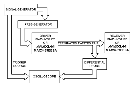
Figure 1. Test setup
System designers often choose drivers and receivers from two different manufacturers. Most designers are most concerned about the transmission distance and speed of RS-485 drivers. The performance of Maxim driver (referred to as MAX3469 here) and other manufacturers' drivers is shown in Figure 2 and Figure 3.
![Figure 2. Eye diagram comparison of Maxim ’s MAX3469 and other RS-485 drivers [3]](http://i.bosscdn.com/blog/20/09/42/416490363.gif)
Figure 2. Eye diagram comparison of Maxim ’s MAX3469 and other RS-485 drivers [3]
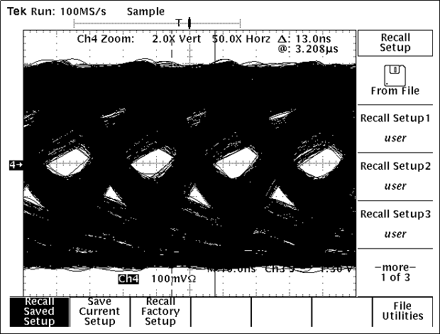
Figure 3. The eye diagram of MAX3469
By observing the integrity of the differential output signal of the driver, use an oscilloscope to determine the toggle threshold between 80mV and -400mV (because the receiver has an input range of 20mV to -200mV and noise margin, this threshold range was chosen). Then, when the pulses (bits) begin to "transmit", the eye diagram is used to determine the degree of distortion, noise, and inter-symbol interference (ISI).
The ISI indicator limits the bit rate to ensure that the system can identify the transmitted data between pulses. The test results of the circuit in Figure 1 show that there is a correlation between the flip threshold and the eye pattern template. The eye diagram template has 50% jitter, which is measured according to the method described in NaTIonal Semiconductor application note 977 [4]. Measure the jitter under 0V differential signal and ± 100mV differential signal to obtain the data shown in Figure 4 and Figure 5.
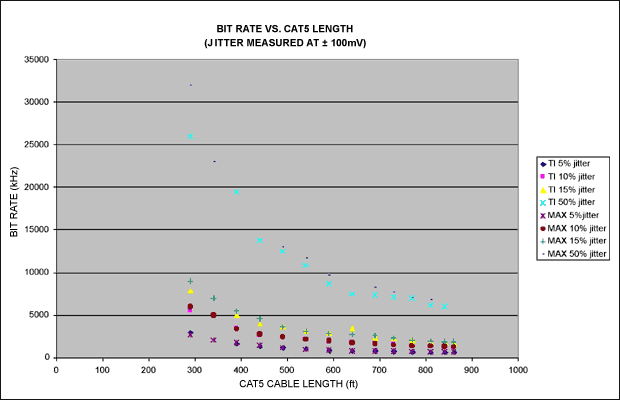
Figure 4. Jitter characteristics at a specific bit rate and cable length. Jitter is measured under ± 100mV differential signals
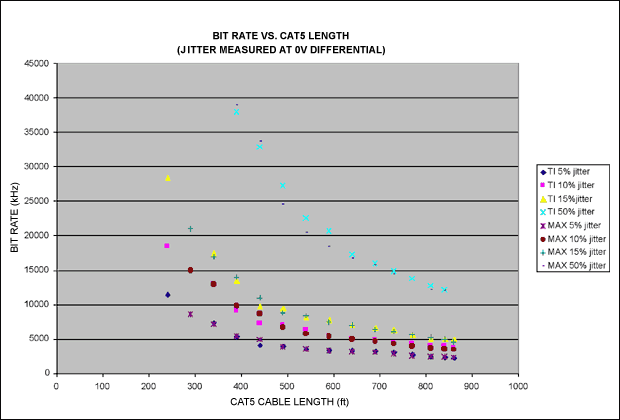
Figure 5. Jitter index at a specific bit rate and cable length. Jitter is measured under a 0V differential signal
For a point-to-point communication system, from the test results under ± 100mV differential signal (Figure 4) or 0V differential signal (Figure 5), the relationship between bit rate and cable length can be seen. The + 100mV and -100mV thresholds can correctly switch signals with differential signals greater than 200mV. Therefore, this threshold can ensure that the receiver receives data correctly (Figure 5 data only applies to ideal receivers that can switch under 0V differential input). The eye diagram and failure mode use 340 feet of Category 5 cable. Figure 2 shows the driver output eye diagram at 39Mbps transmission rate. In the figure, the signal passes through the middle of the "eye"-this situation indicates that bit errors may occur. However, at the same data rate, Maxim's devices will not have this situation (Figure 3). Maxim's transceivers have symmetrical output edges and low input capacitance, and perform well.
Use the above test to compare the two drives. When the data rate is higher and the cable is longer, the performance of the Maxim driver is better. Figure 5 gives estimates of the transmission rate and distance of Maxim devices in a point-to-point network. According to experience, the generated bit errors roughly meet the requirements of the 50% jitter limit. The research data of various parties in the industrial field, the maximum acceptable transmission distance and data rate are generally 4000 feet and 10Mbps, of course, these two values ​​can not be satisfied at the same time. However, with the latest devices and elaborate system design, higher data throughput can be achieved under longer cables.
Pre-emphasis [5] is a technique that improves the relationship between data rate and distance, and can be used for RS-485 communication (Figure 6). Using a 1700-foot cable, operating at a fixed data rate of 1Mbps, RS-485 transceivers without pre-emphasis drivers or equalization receivers typically have 10% jitter. At the same rate, increasing drive pre-emphasis can double the distance to 3400 feet without increasing jitter. Similarly, using pre-emphasis at a certain distance can increase the data rate. At a rate of 400 kbps and a cable length of 4,000 feet, drives without pre-emphasis usually have 10% jitter. With pre-emphasis, the transmission rate at this distance can be increased to 800 kbps.
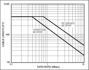
Figure 6. Relationship between data rate and cable length
Another way to estimate the maximum cable length for reliable transmission is to use the table of relationship between amplitude attenuation and frequency provided by Category 5 cable manufacturers. According to the general rules, the maximum allowable signal attenuation when the cable is working is -6dBV. This value is combined with the attenuation data provided by the manufacturer to calculate the maximum cable length at a given frequency. Application Tips RS-485 transceivers have many features to improve system performance: Pre-emphasis (described above): Reduce intersymbol interference Reduce receiver unit load: Low load devices can be as low as 1/8 unit load, allowing on-bus Mount up to 256 devices. This device also reduces bus load, allowing longer cables and higher transmission rates. High-speed devices: drivers with data rates up to 52Mbps are currently available. Such high-speed devices must pay special attention to keeping transmission delays and deviations low. ESD protection: ESD protection will not increase the data rate, but it will improve the reliability of the system when the data rate is 0 (open circuit). At present, it can provide built-in ESD protection of ± 15kV. Correct wiring [6]: RS-485 is used for differential transmission. In addition to the ground wire, two signal wires are required to transmit data (usually 24AWG twisted pair). These two signal lines transmit signals of opposite polarities, which greatly reduces the problems of EMI radiation and EMI interference. The characteristic impedance of the cable is generally 120Ω, which is also the resistance of the matching resistor at the end of the cable-the purpose is to reduce the impact of reflection and other lines. Figures 7 and 8 show the correct system connections.
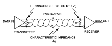
Figure 7. Single-issue / single-receive network
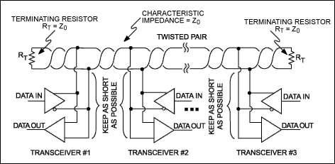
Figure 8. Conclusion of multi-machine transceiver network. In summary, RS-485 network can achieve reliable data transmission in noisy environment. When designing a system, you need to consider the trade-off between data rate and cable length. You can achieve a data rate higher than 50Mbps on a cable that is several hundred meters long without using any repeaters.
A similar article was published on Planet Analog website, June 8, 2005.
references
Maxim Application Note 736: "RS-485 (TIA / EIA-485-A) Differential Data Transmission System Basics". Maxim Application Note 1833: "Using RS-485 / RS-422 Transceivers in Fieldbus Networks". Texas Instruments Databook, "Data Transmission Circuits, Vol. 1," 1995/1996, 4-9 to 4-24, 4-37 to 4-48. National Semiconductor application note 977: "LVDS Signal Quality: Jitter Measurements Using Eye Patterns Test Report # 1" can be found on the company's website. For more details, please refer to Maxim's application note 643: "Pre-emphasis Improves RS-485 Communications". Please refer to Maxim's application note 763: "Guidelines for Proper Wiring of an RS-485 (TIA / EIA-485-A) Network".
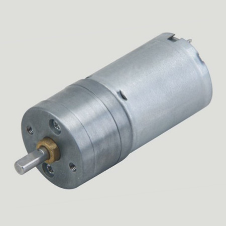
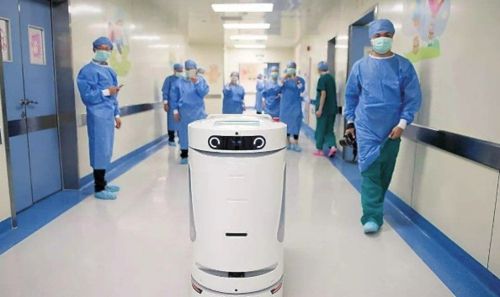
Gear Reducer Motor is a small precision reducer, and the size and specification can be customized below 38mm. Shenzhen shun cheong electrical co., LTD. 15 years engaged in the design, development, manufacture Dc Gear Motor, products applicable to the smart home, widely used in intelligent robot voice interaction, children's education escort robot, intelligent sweeping machine robot, intelligent robot adaptability, independent motor, intelligent medical robot project.
Application field:


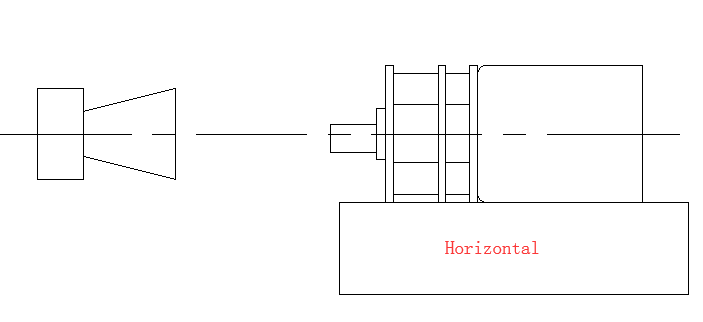
Method of use: the best stable in horizontal plane, installed on the Gear Reducer Motor output shaft parts, cannot use a hammer to knock,knock prone to press into the gear Reducer Motor drive, may cause damage to internal components, and cannot be used in the case of blocked.
Operating temperature range:
Gear reducer motor should be used at a temperature of -10~60℃.
The figures stated in the catalog specifications are based on use at ordinary room temperature catalog specifications re based on use at ordinary room temperature (approximately20~25℃.
If a geared motor is used outside the prescribed temperature range,the grease on the gearhead area will become unable to function normally and the motor will become unable to start.Depending on the temperature conditions ,it may be possible to deal with them by changing the grease of the motor's parts.Please feel free to consult with us about this.
Storage temperature range:
Gear reducer motor should be stored ta a temperature of -15~65℃.
In case of storage outside this range,the grease on the gearhead area will become unable to function normally and the motor will become unable to start.
Service life:
The longevity of gear reducer motor is greatly affected by the load conditions , the mode of operation,the environment of use ,etc.Therefore,it is necessary to check the conditions under which the product will actually be used .The following conditions will have a negative effect on longevity.Please consult with us should any of them apply.
â—Use with a load that exceeds the rated torque
â—Frequent starting
â—Momentary reversals of turning direction
â—Impact loads
â—Long-term continuous operation
â—Forced turning using the output shaft
â—Use in which the permitted overhang load or the permitted thrust load is exceeded
â—A pulse drive ,e.g.,a short break,counter electromotive force,PWM control
â—Use of a voltage that is nonstandard as regards the rated voltage
â—Use outside the prescribed temperature or relative-humidity range,or in a special environment.
â—Please consult with us about these or any other conditions of use that may apply,so that we can be sure that you select the most appropriate model.
when it come to volume production,we're a major player as well .each month,we rurn out 600000 units,all of which are compliant with the rohs directive.Have any questions or special needed, please contact us, we have the engineer group and best sales department to service to you Looking forward to your inquiry. Welcome to our factory.

Gear Reducer Motor
Gear Reducer Motor,Reducer Motor,Gear Reducer Stepper Motor,Dc Reducer Gear Motor
Shenzhen Shunchang Motor Co., LTD. , https://www.scgearmotor.com