FPGA-based frame synchronization system design
The frame synchronization system designed in the scheme was implemented on Xilinx FPGA device XC3S200-4FT200, and the simulation was tested by Modelsim 6.0 software. The simulation results show that the synchronous system designed by this scheme works stably and meets the performance requirements.
0 Preface
In a digital communication system, a transmitting end generally consists of a certain number of symbols to form a "word" or a "sentence", that is, a data frame is formed for transmission, so the frame is a basic unit of data transmission. Different communication systems have different frame structures. The frame is generally divided into two parts: the frame synchronization code and the data. The frame synchronization code is used to mark the start position of the frame; the data is the effective symbol to be transmitted. There are two main methods for inserting frame synchronization code groups: centralized insertion method and interval insertion method. The centralized insertion method is a method of inserting a frame synchronization code group in the beginning of each frame; the interval insertion method is to insert the frame synchronization code group into the data stream, that is, insert a frame synchronization code every certain number of information symbols. yuan. This paper mainly proposes a design scheme of FPGA with centralized insertion method frame synchronization.
In general, frame synchronization can only be done after bit synchronization. Although the frequency of the signal is easily obtained by frequency division of the bit synchronization signal, the start and end times of the frame cannot be determined by the bit synchronization signal. The main task of frame synchronization is to get the start and end of each data frame. With the development of programmable logic devices, digital systems such as frame synchronization using FPGAs have a series of advantages such as high speed, convenient use, and programmable configuration of various parameters, and thus have been widely used.
1 Principle and process of centralized insertion frame synchronization
1.1 Centralized insertion method frame overall structure
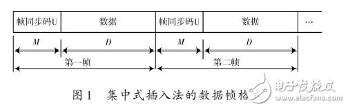
The centralized insertion method refers to a method of inserting a frame synchronization code sequence in the beginning of each frame of data. In this synchronous transmission mode, the transmitted data bits are framed, each frame includes a plurality of data, and the header of the frame is added with a frame synchronization code group (also referred to as a frame flag word), which is denoted as U, and its length. For M (unit: b), the number of data bits in the frame is D. The receiving end searches for the received bit stream, and once the flag word U is detected, the start of one frame of data is known, and accordingly, the frame is The data is grouped to establish a synchronous transmission mechanism. The data frame format of the centralized insertion method is shown in Figure 1.
Obviously, the frame synchronization code group must meet certain conditions: First, the synchronization code group is required to be different from the data to be transmitted as much as possible so as not to mistake the data for the synchronization code group; secondly, the frame synchronization code group has a sharp single peak autocorrelation property. In order to facilitate the correct detection at the receiving end; the third requirement is that the length cannot be too long to avoid consuming too much channel resources. At present, the commonly used frame synchronization code groups mainly have a generalized Barker code sequence, and some systems also use an m sequence with pseudo-random characteristics as a synchronization code group.
1.2 Several states of frame synchronization
According to the principle of frame synchronization search, there is obviously a possibility of false locks (also called false alarm probability) in the frame synchronization search process, because the code sequence formed by the data bits, or part of the logo words and part of the data bits A code sequence of length M may also satisfy the detection condition and is mistaken for U. Therefore, in order to improve the performance of the frame synchronization system (reducing the probability of false locks and increasing the stability of synchronization after locking), engineering usually increases Synchronize the complexity of the process to achieve improved performance. Generally speaking, the process of frame synchronization is divided into three states: search state, calibration state and synchronization state, and its state transition diagram is shown in FIG. 2.
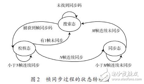
Search state: When the data is received at the start time, or when the frame check occurs, the unsynchronized frame appears, or when the synchronization state is found, when multiple consecutive frames are not synchronized, the search state is entered. In the search state, the program continuously searches for the frame synchronization code in the data stream. When the frame synchronization code is found from the received bit stream, it indicates that a synchronization frame header has been searched, and a pulse signal is outputted, and the system can enter the check. state.
Checking state: If the frame header found in the search state is confirmed by the N frame synchronization code continuously, the system can immediately enter the synchronization state; otherwise, it indicates that there is a false synchronization, and it is necessary to return to the search state to search the frame synchronization code again. The N frame time from the first search to the frame sync header to the sync state is called the back guard time.
Synchronization state: When the frame synchronization system is in the synchronization state, if there is no continuous M frame data that is not synchronized, it remains in the synchronization state. Considering that the received data stream may be subject to external interference and there is a bit error, only the consecutive M frames lose the synchronization code in the synchronization state to enter the out-of-synchronization state and return to the search state. The time of this M frame is called the front guard time.
VHDL design and simulation of 2 frame synchronization system
2.1 Overall structural design
According to the requirements of the instance, the frame synchronization code group length (LenCode), the frame synchronization code group (FrameCode), the fault tolerance number (ErrorNum), the frame length (Len-Frame), the check state check frame number (CheckNum), and the synchronization state The number of core frames (SyncNum) is set in a constant form to facilitate the modification of synchronization parameters in the VHDL program. The system data rate and clock frequency are 50 MHz.
According to the structure shown in Fig. 2, it is easy to think of a state machine design method to implement a synchronization system. Whether using state machine mode or schematic mode for VHDL programming, it can be converted into VHDL code form. Obviously, directly using the form of writing VHDL code is more conducive to program modification and upgrade maintenance. Therefore, this article completely uses code writing to program.
Figure 2 is a typical state transition diagram that can be considered as a signal interface between states. The entire frame synchronization system can be divided into a search status module (Search), a check status module (Check), and a synchronization status module (Sync). In addition to starting the search state after power-on, the search status is also initiated when the check fails (the check frame is not synchronized in the CheckNum frame) or the synchronous state loses lock (the continuous SyncNum frame is not synchronized), so the search status is The start signal has a reset signal (rst), a check state re-search signal (Research_check), and a synchronous state re-search signal (Research_sync); the start signal of the check state is only from the search state (search_over), that is, only when the frame synchronization is searched. After the code is passed, it can be transferred to the check state. If the check is passed, the check completion signal (check_over) is sent. If the check fails, the search signal is sent again (Research_check); the start signal of the synchronous state is only from the check state (check_over). Only after the check is passed can the synchronization state be entered. After entering the synchronization state, the synchronization code group is continuously detected, and when the lock loss is detected, the Research_sync is sent to restart the search state. Figure 3 shows the RTL schematic of the top-level VHDL program file of the frame synchronization system using Synplify Pro.
Xinxiang Mina Import & Export Co., Ltd. , https://www.mina-motor.cn