Demystifying 3G mobile phone RF shielding solutions
The cellular transmitter module will produce the maximum radiated power for any component in the mobile phone, which may induce EMI and RFI. Problems like this can use RF shielding technology to reduce EMI and radio frequency interference (RFI) related radiation, and Can minimize the sensitivity to external magnetic fields. So, what kind of shielding design method has the best efficiency? This three-part series of articles discusses effective RF shielding methods around today's cellular transmission modules.
In recent years, mobile phones have undergone tremendous changes in form, function, performance and cost. New technologies that are constantly evolving have spawned smaller, more energy-efficient and highly integrated semiconductor devices, which has continually bred portable (mobile) mobile phones with higher levels of integration. Operators are providing additional services such as short message service (SMS), multimedia (MMS) and GPS, while manufacturers have added auxiliary wireless functions such as FM radio frequency to mobile cellular phones, as well as other functions such as MP3 players and digital cameras. The form factor and volume required to implement all of these features pose considerable challenges to cell phone designers and hardware engineers.
Therefore, mobile phone designers working at the printed circuit board (PCB) level have encountered undesirable core issues such as coupling between integrated devices, line coupling, and cross-interference. All of these problems have led to more design rework, the lack of versatility between mobile phone shapes and extended design cycles, all of which have increased mobile phone development costs. Under today's competitive market pressure, these factors play a key role in the success of mobile phone manufacturers and the designers who develop them.
One area identified early in the design of mobile phones that can help solve these core problems is the widely used shield. Shielding reduces electromagnetic interference (EMI) and radio frequency interference (RFI), greatly attenuates undesired radiation, and alleviates the disaster it causes. Currently, shielding and RF frequencies follow suit, because all RF communication standards have certain requirements that minimize undesired radiation.
The effectiveness of the shield is characterized by how much it can attenuate the radiated signal in a wide frequency range. For example, a metal "container" with a removable lid can form a shield, or the container itself can be directly soldered to the PCB. The use of the cover structure is very useful for adjustment, so it is often used in applications such as TV tuners, but the effectiveness of the shield is highly dependent on the electrical connection between the cover and the container. It is based on the basic concept that RF shielding is based on: time-varying electromagnetic fields (EM) induce currents around the field lines in the conductor. Therefore, the induced current in a perfect conductor will generate an EM field opposite to the induced field, thereby canceling the field lines in the conductor. Therefore, too many holes, slots and openings in the shield will reduce the shielding effectiveness, because the induced current can only flow in the parts where there are free electrons on the conductor. The opening in the conductor (container) means that there are no free electrons there. It will cause the current to find other ways to flow along the opening, so that the induced field cannot completely cancel the induced field. Epidermal depth is another important factor, which is determined by the ability of EM waves to penetrate the conductive membrane. Especially when low frequencies are of particular importance, a thicker film is needed to effectively shield radiated RF signals.
In this discussion, the key points related to shielding will focus on a common RF semiconductor component in today's mobile phone design-the cellular transmitter module (TxM). In short, TxM consists of mounting bare chips and passive devices on a PCB-like substrate. The component is then overmolded, after which it can be soldered to the mobile phone PCB. This example is particularly useful because it produces the largest radiated power for any component in a cell phone, and is very likely to induce EMI and RFI. In addition, overall, TxM is similar to the rectangular waveguide. According to Pozar [1], the cut-off frequency of the rectangular waveguide is:
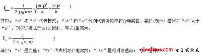
Equation 2 indicates that, as we expected, the cutoff frequency increases as the size of the opening "a" decreases. When there are several openings in the shield, the equation becomes more complicated, further emphasizing the importance of having no openings at all.
Metal shielding containers continue to be used to shield TxM and the RF part of mobile phones from the outside; but recently there is a trend of embedded shielding inside TxM. As far as TxM shielding is concerned, several methods of shielding TxM have been developed. One method is to use an embedded shield made of a simple metal container, but this method requires multiple holes in the container to allow the mold compound to easily flow into the entire module, which is necessary for modular assembly . However, according to the aforementioned waveguide theory, the shielding effectiveness is not only related to the size of the opening on the shield but also to the number of openings. The larger the number of openings, the greater the number, the more severe the reduction in performance.
RFMD has developed a patented MicroShield integrated RF shielding alternative technology. The integrated shield uses a thin layer of metal on the outside of an encapsulated semiconductor injection molding filler as the final step of the entire assembly process. The shielding achieved with this technology has minimal impact on the height of the module and can be repeated in production to reduce EMI and RFI radiation.
To confirm the superior energy efficiency of MicroShield technology, the RF3178 TxM was used to test the radiation on a test carrier (Figure 1).
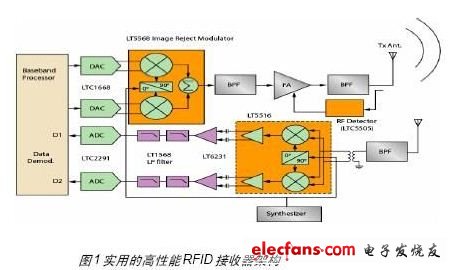
The test results clearly show that the two shielding technologies differ significantly in performance: MicroShield is significantly better than embedded shielding technology. On average, in terms of radiation attenuation, MicroShield integrated RF shielding technology is better than embedded technology by 15dB.
But as a TxM designer, achieving these results is not at hand. From a TxM design perspective, adding shielding poses several problems for designers. First of all, the shielding and electromagnetic radiation circuit next to each other changed the frequency response, and the frequency response was no longer consistent with the "plain (unmolded)", fully adjusted TxM, thereby changing the performance of the shielded circuit. These effects are better observed especially at higher frequencies. In this way, when shielding is added, modeling and EM simulation are extremely important to ensure good results.
Because 3D EM simulation can be time-consuming, depending on the complexity of the circuit and the number of tetrahedral components that need to be provided with sufficient accuracy, starting with a less complex circuit and confirming its important key parts will not work Tang donated. For example, it is not difficult to draw from the field theory: the closer the two carrier field signal lines are to each other, the more they tend to produce greater coupling. These signal lines carry time-varying charges, which are already embedded in the substrate and covered with metals such as ground planes, so that when an external shield is applied, it does not substantially show additional interference on the field lines. Only signal lines, components, or wire bonds face significant changes in their respective field lines, because these elements are exposed to air or are overmolded as boundary conditions.
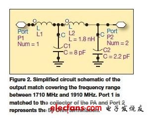
Figure 2 shows the output matching of the power amplifier section with a package injection mold TxM. It has two cases: no shielding and applying a shield on the package injection mold. The dual-port simulation is implemented using Ansoft's 3D EM software tool HFSS.
Although output matching only represents a small part of the passive circuit within the entire TxM, it is still effective in determining the coupling mechanism and the effects of higher-order harmonics.
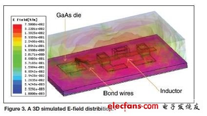
The second focus is on the field lines near the microstrip line, where they are strongest near the ground plane. As long as the distance between the shield and the ground plane is significantly greater than the distance between the microstrip line and the ground plane, the effectiveness of the added shield is minimal. The direct coupling of wire bonding and surface mount inductors to the ground plane is weaker. When shielding is applied, the field lines are expected to change. Figure 3 shows the 3D simulated E-field distribution.
Battery Formation Charger,Discharger Testing Machine,Battery Formation Machine,Formation Charger/Discharger
Zhijiang BSL battery technology service company , https://www.bslbatteryservice.com