Extremely flexible automotive LED headlamp solution with laser channel
Abstract: As the world continues to seek smarter automotive lighting systems and save energy, automotive lighting has become an area of ​​innovation and improvement. Today's automotive solid-state lighting (ASSL) systems come with a variety of types of loads, including LEDs, OLEDs, laser diodes, etc. Engineers need to find more flexible platform solutions to efficiently and flexibly drive these loads in a single system.
LED headlamps with laser channels are a typical application scenario. The illumination control unit (LCU) shares the output of a boost circuit to simultaneously drive the laser channel and the daylight running light (DRL) channel. This method is not very efficient, it causes additional heating of the laser channel because the laser channel shares the same voltage with the DRL, causing the driving voltage of the driving laser channel to be higher than the actual required voltage.
This article will examine how to solve this problem using NXP's automotive solid state lighting driver ICs. The driver IC provides two independent voltages that can be individually controlled via the SPI interface. This article makes it easy to see the improvements brought about by this innovative structure through two application examples and a comparison between system-level efficiency and laser channel efficiency.
Background introduction
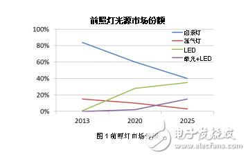
Since the introduction of LED and laser diode technology a few years ago, automotive headlamps have grown rapidly. LED luminaires with laser channels typically have an adaptive headlight illumination system (AFS) function or a matrix beam that is now increasingly popular with OEMs. This is not only because they are energy efficient, but also because they do not produce glare and can expand the range of high beam. The LED headlamps with laser channels have been supported by major OEMs such as BMW and Audi and LED suppliers such as OSRAM in Europe, so the development is particularly rapid. According to Driving Vision News 2014's forecast of market share trends in headlights, the market share of LEDs and laser headlamps will increase rapidly from 2020 to approximately 18% by 2025.
Lighting control unit
The Lighting Control Unit (LCU) is a key component of laser LED headlamps and features laser-based illumination, AFS, dynamic adjustment or matrix control. A typical embodiment is shown in Figure 2 below.
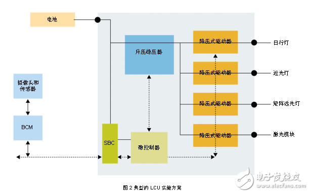
The driver module typically includes a microcontroller (MCU) and a transceiver in communication with the body control module (BCM). By analyzing the signal sent by the camera or sensor to sense the traffic condition, the BCM sends an instruction to the MCU, and the MCU controls the driver IC through the SPI interface. The power stage typically employs a two-stage topology that uses a boost regulator circuit and a separate buck channel to drive the LED or laser diode for different illumination functions.
2. Power stage design
As shown in Figure 2, this two-stage topology allows the voltage source to remain stable under a variety of conditions, such as load dump and cold start events, while still responding quickly to load dynamics at each stage. This feature is critical for matrix or full LED headlamp designs. However, when using these two levels of architecture design, how to select external components for different buck channels is a headache. For example, the buck channel that drives DRL has a relatively low output current of 0.2-1 A, but the voltage is high: therefore, the MOSFET drain-to-source voltage (VDS) and diode reverse leakage current are important. However, the output current of the buck channel that drives the laser channel is relatively high, greater than 1 A, and the VF is relatively low: therefore, the MOSFET drain-source on-state resistance (Rdson), inductor DC resistance (DCR), and diode forward voltage are even more important. Obviously, it is difficult to drive all of these channels with a single boost voltage. For this solution, two independent boosts can be used, even one boost voltage plus one SEPIC voltage (included in one controller IC). This advantage comes from the chip's powerful digital regulation loop design. Two application examples are shown below, clearly demonstrating system efficiency and improved laser channel efficiency.
*Application Example 1: Let's look at the design example of a 60 W LCU, which uses three sets of loads: 54 V/540 mA DRL, 16 V/0.5 A fog lamp, 8 V/2 A laser module, as shown in Figure 3. Shown.
- Solution 1: Design 63V boost for all three sets of bucks. Using a two-phase parallel boost voltage to drive 60W simplifies the MOSFET and inductor design process.
- Solution 2: Design a 63 Vboost1 for DRL and another 35 Vboost2 for fog lamps and laser modules.
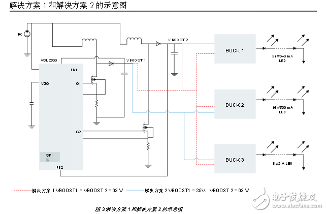
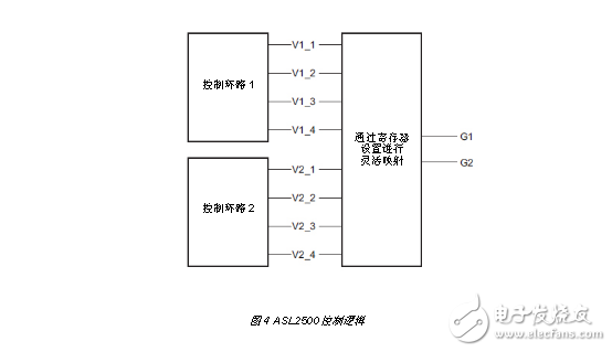
In the solution shown in Figure 3, we use the ASL2500 as the drive control IC. The ASL2500 contains two independent internal control loops (Figure 4), which are treated as virtual phase logic 1 and virtual phase logic 2, respectively. Different phase assignment registers can be programmed with the SPI to connect the two physical drive stages to the internal virtual phase without the need to use additional components to determine how to allocate. The output of the boost circuit can drive the same output voltage in parallel or drive two independent output voltages.
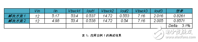
From the evaluation results shown in Table 1, we can see that the solution efficiency of Solution 2 is 3% higher than that of Solution 1: It is equivalent to saving 1.8 W of heat in the 60 W LCU design. Considering the small size of the LCU, this is significant for simplifying the thermal design.
*Application Example 2: This example uses a 60 W LCU design with three sets of loads: 52 V/320 mA DRL, 15 V/0.55 mA fog lamp, 8 V/3 A laser module, as shown in Figure 4.
- Solution 3: Design 63 V boost for DRL 52V/320mA and fog lamp 15V/0.55mA, 9.5V SEPIC for laser module 8V/3A
- Solution 1: Design 63V boost for three sets of bucks. Using a two-phase parallel boost to drive 60W simplifies the MOSFET and inductor design process.
Magnetoelectric Proximity Switch
The magnetic proximity switch is a kind of proximity switch. The magnetic proximity switch is one of many types in the sensor family. It is made by the use of electromagnetic working principle and advanced technology. It is a position sensor. It can transform the non-electricity or electromagnetic quantity into the desired electric signal through the change of the positional relationship between the sensor and the object, so as to achieve the purpose of control or measurement.
Motion Sensor Control Switch,Photoelectric Switch Sensors,Plug In Photoelectric Switch,Magnetoelectric Proximity Switches
Changchun Guangxing Sensing Technology Co.LTD , https://www.gx-encoder.com