Embedded controller based on Atmega128 microcontroller design
The embedded controller is built around the Atmega128 microcontroller, which features an on-chip analog-to-digital converter for handling analog input signals. For output, the system uses the AD421 digital-to-analog converter, while high-speed optocouplers are employed for digital I/O channels. To support real-time operations, the LCCavr compiler's OSTaskStkInit() function and related files were modified, along with the definition of specific data types, to enable the migration of the MICROC/OS-II operating system.
1 Introduction
Embedded controllers play a crucial role in the automation of electromechanical systems. In this design, a high-performance Atmega128 microprocessor is used as the core component to develop a multi-functional, intelligent embedded controller that supports fieldbus communication via CANBUS and offers flexibility for various applications. This controller is particularly suitable for large-scale electromechanical equipment where reliability and performance are essential.
2 Hardware Design
The overall hardware architecture of the system is illustrated in Figure 1.
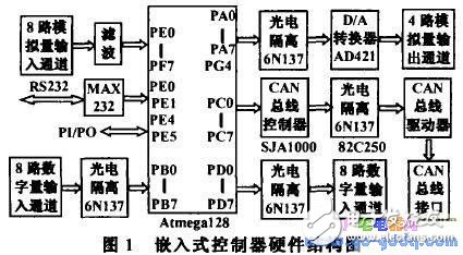
At the heart of the controller is the Atmega128 microcontroller, housed in a 64-pin TQFP package. It provides 53 programmable I/O pins, along with 128KB of flash memory, 4KB of EEPROM, and 4KB of SRAM, making it ideal for complex control tasks and sufficient storage requirements.
(1) Analog Input Channel
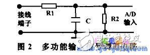
The analog input section utilizes the 8-channel, 10-bit ADC integrated within the Atmega128. Depending on the type of signal being measured, different signal conditioning circuits can be selected. For voltage inputs, R1 and C form a low-pass filter when R2 is open. When dealing with a 4-20 mA current signal, R2 is set to 250Ω to convert it into a 1–5V range. These configurations are implemented using soldered components on the board, allowing users to choose the appropriate setup for their application. The analog input channels are connected to PF0 through PF7 of the Atmega128.
(2) Analog Output Channel
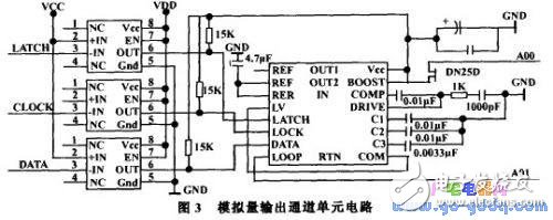
The analog output channel employs the AD421 DAC from Analog Devices. This single-chip, low-power, high-precision current-output DAC is capable of driving standard industrial actuators with a 4–20 mA output. The device supports HART or other FSK protocols and has a 16-bit resolution with monotonic output. It is loop-powered and includes an internal power regulator. For this design, four AD421s are used, each connected via optical isolators (6N137) to PA3–PA7 and PE2, PE3, PE6, PG4 of the Atmega128, enabling four independent analog output channels.
(3) Digital I/O Channels
Each digital I/O channel is equipped with eight high-speed optocouplers, specifically the 6N137 model. This optocoupler has a switching delay of only 75ns, significantly faster than conventional optocouplers that typically have delays between 3–6μs. The digital I/O interface is connected to PB0–PB7 and PD0–PD7 of the Atmega128, providing a robust and reliable connection for external devices.
(4) CAN Bus Interface
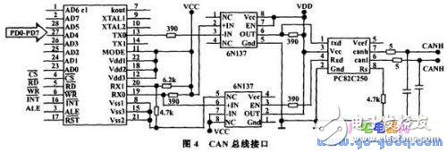
The CAN bus interface is designed using the SJA1000 CAN controller, the 82C250 CAN transceiver, and high-speed optocouplers (6N137). The Atmega128 manages the initialization of the SJA1000 and handles data transmission and reception through its control signals. The SJA1000’s AD0–AD7 are connected to the PC port of the Atmega128, while CS is connected to PG3. When PG3 is low, the CPU accesses the SJA1000’s memory space. The RD, WE, and ALE signals of the SJA1000 are connected to corresponding pins on the Atmega128, and the INT pin is linked to PE7, enabling interrupt-driven communication.
(5) Serial Communication with PC
To support communication with a PC, the Atmega128’s serial port is configured for interrupt-based data reception. The PE0 and PE1 pins are used for RS232 communication, and a MAX232 chip is employed for level conversion. This allows the controller to receive and process commands or data from a host computer efficiently.
(6) Pulse Input and Output
Due to the variety of input signals, additional pulse input and output capabilities are included. This enhances the system’s versatility, making it suitable for applications involving pulse width modulation, frequency measurement, or other time-based signals.
The motor wire also apply to automotive, bus, bike, truck. Yacenter have 19 years experience in wire harness industry, cooperate with Nisson, BMW, GM, HONDA, Mitsubishi
Yacenter has experienced QC to check the products in each process, from developing samples to bulk, to make sure the best quality of goods. Timely communication with customers is so important during our cooperation.
If you can't find the exact product you need in the pictures,please don't go away.Just contact me freely or send your sample and drawing to us.We will reply you as soon as possible. Please tell us what kind of model you need (including the drawings, specification, or samples) , then the price will be sent to you soon.
Motor Wiring Harness,Motors Radio Wiring Harness,General Motors Wiring Harness,Motor Power Wiring Harness
Dongguan YAC Electric Co,. LTD. , https://www.yacentercn.com