Chongqing Yuelai Exhibition Phase II Power Monitoring System
0, Overview
Chongqing Yuelai Convention and Exhibition Center, also known as the Chongqing International Expo Center, is a modern smart complex that combines exhibition, conference, catering, accommodation, performing arts, and event management. It is the largest professional venue in western China. Located beside the Jialing River, surrounded by mountains and rivers, with nearby parks and ancient towns, it offers a beautiful environment where nature, city life, and greenery blend seamlessly. This unique space serves as a park pavilion, cultural exhibition hall, and ecological center. The total construction area of the exhibition center is 600,000 square meters, with an indoor exhibition area of 200,000 square meters. It includes 16 exhibition halls—eight in the north and eight in the south—making it the second-largest in the country and first in the west.
This project is the second phase of the power monitoring system for the Pandai Exhibition. According to the requirements of the power distribution system, it is necessary to monitor the low-voltage power distribution room of the second phase of the Wyatt MICE project to ensure safe, reliable, and efficient electricity usage.
The Acrel-2000 low-voltage intelligent power distribution system utilizes the latest advancements in electronic technology, computer science, network communication, and fieldbus systems. It enables distributed data acquisition and centralized monitoring and management of the power distribution system. Secondary equipment is networked, connecting the distributed devices at the distribution center into a unified system through a computer and communication network, allowing remote monitoring and centralized management of the power grid operation.
1, System Structure Description
In this project, there are a total of 50 smart meters. The collection device is located in the power distribution room. On-site comprehensive protection devices and smart meters are connected to the serial port server via the 485 bus. The serial port server then transmits the data to the monitoring host through network cables.
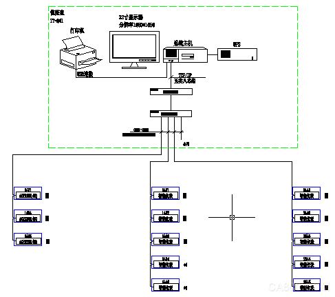
The monitoring system adopts a hierarchical distributed structure, consisting of three layers: the station control layer, communication layer, and bay layer.
The bay layer mainly includes multi-function network power meters, smart motor protectors, and similar devices. These devices are installed in electrical cabinets and communicate via RS485 interfaces through a local MODBUS bus network to collect on-site data.
The communication layer primarily consists of industrial serial servers. Their main function is to collect scattered data from field devices and transmit it to the station control layer, enabling data exchange between the field and station control layers.
The station control layer is equipped with high-performance industrial computers, monitors, UPS power supplies, printers, and other equipment. The monitoring system is installed on the computer to collect and display the operating status of field equipment, presenting it to users through human-computer interaction.
All field devices use RS485 interfaces and the MODBUS-RTU communication protocol. RS485 transmission uses shielded cables, typically with two connections for simplicity. The communication interface is half-duplex, allowing either sending or receiving data at a time, with a maximum data transfer rate of 10 Mbps.
The RS485 interface combines balanced drivers and differential receivers, offering enhanced noise immunity and supporting up to 32 devices on the bus. The maximum transmission distance is 1.2 km.
2. Main Functions of the Power Monitoring System
2.1 Data Acquisition and Processing
Data acquisition is the foundation of power distribution monitoring. It is mainly accomplished through multi-function network instruments at the lower level, enabling real-time remote data display. Collected signals include three-phase voltage U, three-phase current I, frequency Hz, power P, power factor COSφ, energy Epi, and the operational status of remote devices.
Data processing displays collected electrical parameters in real time and accurately according to user requirements, meeting automation and intelligence needs for power distribution monitoring. It also stores collected data in a database for user queries.
2.2 Human-Computer Interaction
The system provides a simple, user-friendly interface. Using a Chinese interface, it shows the main wiring diagram of the low-voltage distribution system via CAD graphics, displaying the status of distribution equipment and real-time operating parameters. It supports screen timing switching, dynamic real-time refresh, analog display, switch display, and continuous recording display.
2.3 Historical Events
The historical events interface provides users with an easy-to-use human-computer interaction experience by viewing fault records, signal records, operation records, and over-limit records. Users can access historical events and locate faults based on their requirements. This feature offers solid software support for overall system operation.
2.4 Database Establishment and Query
It completes remote measurement and signal acquisition, establishes a database, and generates reports regularly for user query and printing.
2.5 User Rights Management
Different permission groups are set for different user levels to prevent losses caused by human error and ensure the safe and reliable operation of the distribution system. User management allows login, logout, password change, and add/delete operations, facilitating account and permission modifications.
2.6 Running Load Curve
The load trend curve function collects incoming line and important loop current and power load parameters regularly, automatically generating running load trend curves to help users monitor equipment load status in real time. Users can switch functions by clicking buttons or menu items, view real-time or historical trend lines, and perform translation, zoom, and range conversion on selected curves to assist in trend analysis and fault recall, providing intuitive software support for system operation.
2.7 Remote Report Query
The report management program designs report styles according to user needs, filters, combines, and statistically processes system data to generate required report data. It also allows users to save, print, or call report files based on their needs. Additionally, it provides management functions for generated report files.
Reports allow users to freely set query times for daily, monthly, and annual energy statistics, data export, and report printing.
3, Case Analysis
The multi-functional power meter used in this project is designed for power monitoring in power systems, industrial and mining enterprises, public facilities, and intelligent buildings. It measures conventional power parameters such as three-phase voltage and current, active power, reactive power, power factor, frequency, and active/reactive power.
The secondary map of low-voltage power distribution is shown in Figure (1). The function power meter telemetry mainly monitors the electrical parameters of the operating equipment, including line three-phase voltage, current, power, power factor, energy, frequency, and three-phase current. The remote signal function displays the operating status of field devices, including switch status, closing operations, and communication failure alarms. When a circuit breaker trips, it sends an alarm signal to alert the user to handle the fault promptly.
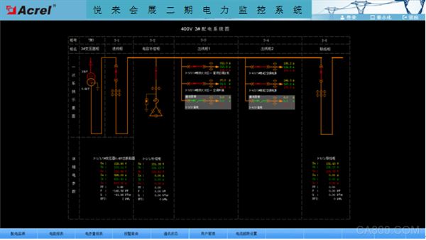 Figure (1) Low-Voltage Distribution Diagram
The parameter reading function mainly queries the electrical parameters of the low-voltage outlet circuit. It supports real-time electrical parameter queries, with features like data export and report printing. The report queries the electrical parameters of the four transformer substations of the two substations, mainly including three-phase current, active power, and transformer temperature. The loop names in the report are associated with the database, making it easy for users to modify loop names. See Figure (2).
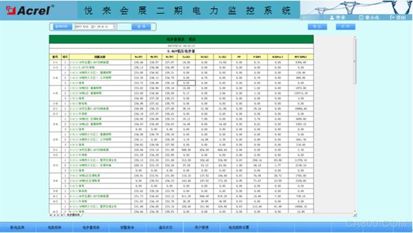 Figure (2) Parameter Reading
The schematic diagram of the system communication structure mainly shows the system's networking structure. The system uses a hierarchical distributed structure and simultaneously monitors the communication status of equipment at the bay level. Red indicates normal communication, while green indicates a communication failure. See Figure (3).
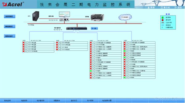 Figure (3) System Communication Structure
4, Conclusion
With the development of society and the widespread use of electricity, power monitoring systems have become an essential choice for large-scale multi-substation users, such as key construction projects, landmark buildings, and large public facilities across the country. The Acrel-2000 power monitoring system introduced in this paper has been applied in the second phase of the Chongqing Yuelai Convention and Exhibition Center. It enables real-time monitoring and power management of low-voltage distribution circuits in the substation. It not only displays the power status of the distribution circuit but also has network communication capabilities, uploading electricity data to the next-level platform. The system analyzes and processes the collected data, displaying the real-time status of each distribution circuit in the substation. It includes pop-up alarm dialog boxes and voice prompts for load changes, and generates various energy reports and analysis curves, graphs, etc., to facilitate remote meter reading and analysis. The system is safe, reliable, and stable, providing real and reliable basis for users to solve electricity problems and achieving good social benefits.
References
[1]. Ren Chengcheng, Zhou Zhong. Principles and Application Guide for Digital Meters for Electric Power Measurement [M]. Beijing. China Electric Power Press, 2007. 4
[2].Zhou Zhouzhong, et al. Product Selection and Solution for Smart Grid User-end Power Monitoring and Power Management System[M]. Beijing. Machinery Industry Press. 2011.10
About the Author
About the author: Wu Haiying, female, undergraduate, Ankerui Electric Co., Ltd., the main research direction for the smart grid power distribution. Email: Mobile QQ
YIWU JUHE TRADING COMPANY , https://www.nx-vapes.com