Design of new non-magnetic water meter with 32-bit MCU series
Introduction of a new non-magnetic water meter scheme based on Silicon Labs MCU
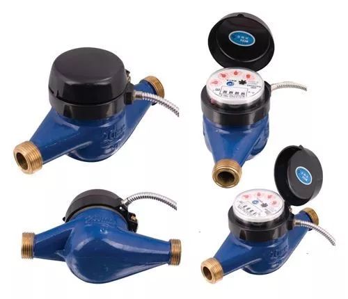
With the development of the times, smart water meters have replaced some traditional mechanical water meters and have been widely used. The measurement method of smart water meters has become more and more diversified with the development of electronic technology. Mechanical head detection, ultrasonic detection, and magnetic detection have been successively introduced. However, these methods have obvious limitations: they are susceptible to external electromagnetic interference or due to the cumulative adsorption of impurities by the permanent magnets in the water, causing measurement errors or being artificially utilized, resulting in leakage and accounting. Under this circumstance, the advantages of non-magnetic metering water meter are remarkable, and it is favored by the majority of water meter manufacturers because of its high measurement accuracy, non-magnetic, no impurity adsorption, and no human interference.
For the design of the new non-magnetic water meter, Silicon Labs (also known as " core technology " ) agent partner Beineng International wrote this article to discuss the integration of Low Energer Sensor based on Silicon Labs ' EFM32 series 32 -bit MCU . On the basis of the design, it is convenient to realize the technical scheme of non-magnetic water meter measurement. In addition to water meters, gas metering and heat metering are also very feasible.
Introduction to the principle of non-magnetic detection
The basic principle of the non-magnetic water meter is the LC oscillation sensor, as shown below:
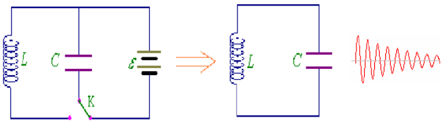
LC oscillation circuit
In this circuit, through the switch K adjustment, a sine wave output circuit can be realized on the LC circuit, and the capacitor C is charged by K. After being fully charged, K is connected to the inductor L , and the amount of the capacitor will be discharged through L because of the inductance. L' s power consumption, so it will present a gradually attenuating sine wave output.
Using this principle, a non-magnetic water meter achieves metering by detecting the sinusoidal attenuation process. In the circuit to the right of the figure below, the disk represents the dial rotor of the water meter, the dark area represents the metal dial area, the white area represents the non-metallic dial area, and L is the fixed inductor coil. After charging the LC circuit, the MCU can obtain a sine wave in the LC oscillating circuit by detecting the voltage across the fixed capacitor C.
When the inductor coil is in the metal zone, an inductor eddy current is formed, resulting in greater power consumption, and the sine wave decays faster; when the inductor coil is in the non-metal region, there is substantially no eddy current, and the sine wave decay speed is relatively slow. Through the MCU to detect the speed of the sine wave attenuation, it can accurately identify which area the dial rotor is in, and then determine the position and number of the dial to achieve the purpose of metering.
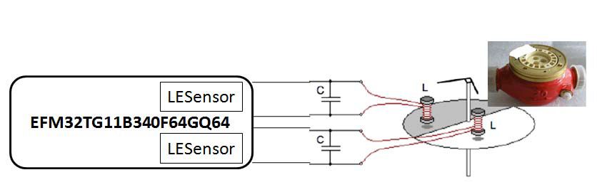
Schematic diagram of water metering non-magnetic detection
The non-magnetic detection is realized by two LC oscillation circuits. The following figure shows the sinusoidal attenuation variation process corresponding to the LC oscillation during the rotation of the dial .
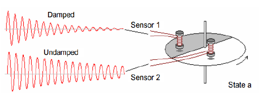
Rotor state A corresponds to the attenuation waveform
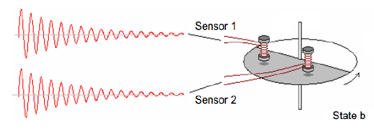
Rotor state B corresponds to the attenuation waveform

Rotor state C corresponds to the attenuation waveform
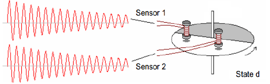
Rotor state D corresponds to the attenuation waveform
Through analysis, the Sensor1/Sensor2 state is obtained during the rotation of the rotor at A ( 0/1 ) -> B ( 0/0 ) -> C ( 1/0 ) -> D ( 1/1 ) -> A ( 0 / 1 ) ->B ( 0/0 ) ->C ( 1/0 ) ... The middle loop appears. We obtain the corresponding state by detecting the sine wave attenuation trend of Sensor1/Sensor2 , and then pass the different combined states (A: fast / Slow B: Fast / Fast C: Slow / Fast D: Slow / Slow ) to get the speed of the water meter.
Low level means fast decay, high level means slow decay, and the following relationship is obtained:
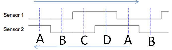
Sensor detection position logic diagram
So the key question is, how does the MCU detect the status of Sensor1 and Sensor2 more effectively , and make the process simpler, faster, and lower power? SiliconLabs company 32bit MCU built-Low Energer Sensor Module, will provide us with a tailor-made for the measurement of non-magnetic detection scheme.
MCU platform introduction and program block diagram
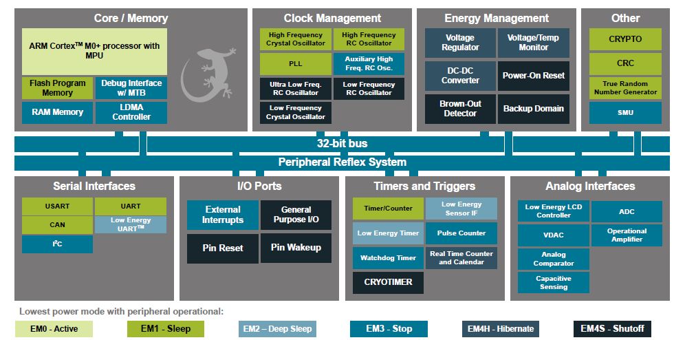
SiliconLabs ' high-performance MCU EFM32TG11B340F64GQ64 is based on ARM Cortex-M0+ core MCU , designed with the latest 90nm new process, operating at 48MHz ; ultra-low power, 51 μA/MHz @ 3VSleep Mode , 5 low-power modes can be flexibly satisfied various power design requirements; 32K of Flash space, 4K SRAM; rich peripherals facilitated the integrated design, the internal integration of the optional ultra-low power LCD driver up to 8 * 20 Dan; integrated internal comparator / operational amplifier , 12bit ADC module and a 12bit DAC, the DAC can be configured to output the reference voltage input to the comparator; 8-channel DMA greatly improve system efficiency, rich communication interface; plus a low power dual serial port low Energy UART, IIC / SPI can support Work in DMA mode; flexible encryption algorithm, support automatic random number; provide high-speed low-power RTC and RTC backup power interface; Low Energer Sensor module can realize capacitance / inductance / power change detection and wake-up mechanism; strong anti-interference Stable performance.
In the non-magnetic water meter products, non-magnetic detection and low-power design are difficult, and the Low Energy Sensor module inside the MCU simplifies the algorithm for non-magnetic detection and reduces the system power consumption. At the same time, the chip is highly integrated. The peripherals enable the non-magnetic water meter design to achieve high integration, reduce the size, reduce the cost, and the products are more competitive in the market.
SiliconLabs development environment Simplicity Studio supports a variety of standard C compilers Keil / IAR / Hi-teck, etc., using the configurable programming tool SimplicityConfigurators , flexible and convenient, suitable for new users to quickly get started.
EFM32TG11Bxxx internal block diagram
The design block diagram of the program is as follows:

Non-magnetic water meter scheme block diagram
Introduction to Low Energy Sensor
The LowEnerger Sensor is a standard peripheral in Silicon Labs ' high-performance 32 - bit MCUs , from the ARM Cortex -M0+ to the M3/M4 series. It is a measurement sensor formed by combining several different existing peripherals. It can be used to measure changes in inductance / capacitance / electricity. It simulates the analog data collected by the comparator and is generated by a high-precision DAC . The reference voltage is compared, and the level of the input voltage and the reference voltage are judged by comparing the flip logic, and the output result is the number of flips. These results are stored in the set area, and processed by the preset timing logic, counting processing, thereby passing through The second result analysis is used to determine the variation of the sampled analog waveform.
With the Low Energer Sensor , almost all sensor interface tasks using analog comparators, DACs, and counters are handled automatically when the EFM32TG11Bxxx is in EM2 (deep sleep mode) . A wake-up to EM0 (operating mode) is required only when the sensor reading changes and the trigger threshold is reached, or when a higher level of calibration is required , greatly simplifying the product's low power design requirements. In EM2 mode, the MCU current parameter is about 1.54μA .
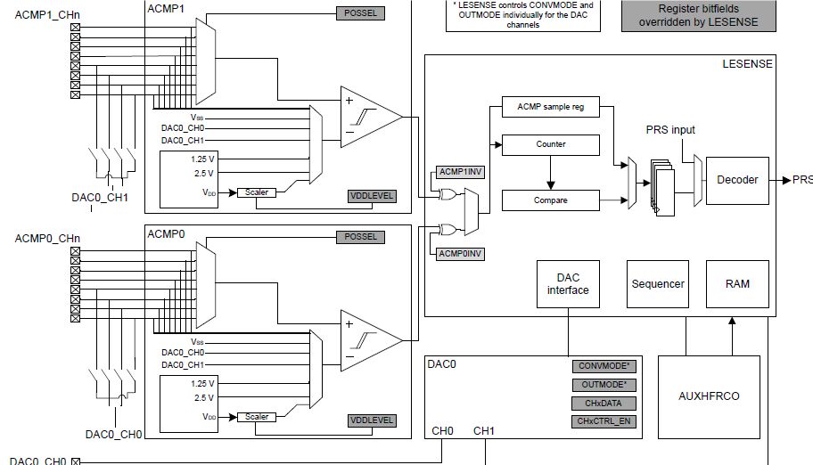
LowEnerger Sensor module block diagram
Low Energy Sensor implementation without magnetic detection
After charging the LC circuit, the charging circuit is disconnected, and the oscillation of the LC circuit has a stable process. This process requires a Delay delay in the detection algorithm to avoid detection and prevent false positives.
1, charging: Low EnergerSensor to charge capacitor C in the LC circuit. The charging time is very short, the capacitor is charged by the DAC0-CHx switch, and the timing is disconnected.
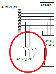
Charging switch icon
2 , delay: sine wave attenuation is very slow just after charging for a period of time, this time requires a delay, waiting for a regular decay period, this delay is adjusted according to LC parameters and inductor eddy current size, Appropriate values ​​need to be obtained through experimental testing.

Time delay icon
3. Detection: After the delay, the Low EnergerSensor needs to determine the decay speed of the sine wave at this time, and thus determine the state of Sensor1 and Sensor2 to obtain the rotor position. Because the received sine wave, the LowEnerger Sensor measures through the comparator and determines the attenuation by adjusting the comparator reference voltage. For example, the detection diagram: the red reference line in the figure is the reference voltage point adjusted by the DAC . The reference point can be adjusted by the DAC according to the actual parameters to adjust the reference point.
It can be seen that, adjusted to the appropriate reference point, the Sensor in the metal zone is faster because of the faster decay, so the voltage is below the reference line, and the corresponding comparator flips less. The Sensor in the non-metallic zone is less attenuated. Slow, the voltage decays below the baseline for a relatively long time, and the corresponding comparator flips more times.

Detection icon
4 , processing: the rotor position obtained this time, and the last time to obtain the location for analysis, in line with the smooth or reverse logic is reasonable, once it does not meet the change logic, it is invalid measurement, need to check or restart detection. Low Energer Sensor can achieve the above steps through software settings, without the need for the customer to implement the combined peripherals and control logic through the software, and automatically enter the IDIE mode after the measurement is completed , greatly improving efficiency and reducing power consumption.

Low Energer Sensor processing logic diagram
Other functional applications
LCD driver (optional): The LCD driver can drive up to 8x32 segmented segment LCD displays. The voltage boost function allows it to provide an LCD driver power supply that is higher than the supply voltage . A dedicated charge redistribution driver is also provided to reduce the 40% LCD drive supply current. In addition, animation is also supported, allowing you to run custom animations on the LCD without any CPU intervention.
Dual serial communication: It can realize communication with the host computer and add the meter reading module / communication module. It is flexible in use and also provides a LowEnergyUART , which can work at the baud rate of 9600bps under the 32.76K clock , improving efficiency and reducing power consumption.
Other functions: PWM drive : efficient motor opening and closing ; 12bitADC: battery power detection and motor overcurrent protection.
Program advantage
Silicon Labs ' high-performance, high-stability MCU EFM32TGxxx , a highly integrated peripheral, enables a low-cost, low-power, single-chip, non-magnetic water meter solution that is more power- and integrated than the current non-magnetic approach on the market. , cost, performance and other aspects have obvious advantages, I believe that with the advancement of the non-magnetic water meter market, this program will gradually become one of the market-leading solutions, designing more advantageous products for customers.
Beineng International Co., Ltd., which is based on technical service customers, has launched this new non-magnetic water meter solution and will provide customers with comprehensive support in technical support, including Silicon Labs MCU development platform, non-magnetic detection algorithm and hardware design evaluation. , software algorithm guidance and other technical assistance, fully assist customers to complete the mass production of non-magnetic water meter program.
The non-magnetic detection scheme has obvious performance and cost advantages, flexible design, and greatly reduces the difficulty and power consumption of the non-magnetic detection technology, and is applicable to other similar metering schemes such as gas meters and heat meters.
references:
1 , EFM32TG11 FamilyData Sheet https://
2 , Low Energy SensorAN0029 - Application Note https://
3 , based on single-chip magnetic sensorless water meter design sensor and micro system 2006 03:54-56
Multi function remote manual pulse generator for control of all axes.
Manual Sensor,Miniature Optical Kit Encoder,Rotary Encoder With Led Ring,Optical Quadrature Encoder
Yuheng Optics Co., Ltd.(Changchun) , https://www.yuhengcoder.com