Click suppression scheme in set top box
When the TV is turned on, if the set-top box (STB) is turned on or off, annoying clicks and other noises are heard from the TV speakers. This noise can be very harsh and the size of the sound depends on the volume setting. Due to customer demand for improved system performance, set-top box design engineers have been looking for ways to suppress these noises.
This article refers to the address: http://
The reason for the noise is that when the power state of the set-top box changes, a voltage offset occurs on the audio output line of the set-top box. The clicks produced by the speakers are usually some transient audio signals. The structure of the audio amplifier, the AC coupling of the audio signal, and the characteristics of the set-top box power supply can all lead to this result. It seems unlikely that the noise will be completely eliminated at all, but MaximIC with direct drive technology can greatly reduce the noise in the STB. In the past, engineers only used subjective estimates to evaluate the transient noise of STB audio output. This article introduces a more objective and easily accepted measurement method.
Let's first discuss the main sources of noise and then introduce ways to eliminate noise. Use the correct method and tools to illustrate the test method by measuring two different audio amplifier chips in the SCART STB.
1 Source of clicks in the set-top box
The main cause of the click is the AC coupling capacitor at the output of the set-top box. The STB's audio amplifier and codec (CODEC) are powered from a single supply, so the audio signal must be biased near the mid-level between the power supply and ground potential. Otherwise, the amplifier's internal circuitry may not work properly. Therefore, the STB output needs to provide a DC offset to the audio signal.
Since the load (television) is referenced systematically, the voltage difference between the load and the amplifier produces a DC current path. An AC coupling capacitor is required to block the DC path between the load and the amplifier output. In addition, this capacitor provides protection for the audio amplifier when externally shorted (the audio jack is exposed to the outside, and the user may inadvertently cause a short circuit when connected). The ac coupling capacitor provides good isolation and protection for the STB, but in a new generation of amplifiers, the short circuit protection circuit eliminates the need for ac coupling capacitors.
When the audio amplifier is turned on/off, the output voltage rises/falls to the bias voltage (or ground potential). The slope of the charging and discharging of the coupling capacitor depends on the magnitude of the capacitance and ultimately determines the frequency of the transient noise. Some designers mistakenly believe that choosing the right capacitor and increasing the charging slope can move the noise out of the audio band, and further investigation shows that this method is not so simple.
First, the initial slope of the output rise to the bias voltage depends mainly on the current drive capability of the amplifier's output stage, and the magnitude of the capacitor only changes the output rate of change with the up and down fluctuations of the power supply (at bias voltage and ground potential). between). The steep edge of transient noise is generated when the amplifier is powered up, while the slower edge (the transient signal returns to ground) is affected by the magnitude of the capacitance.
Another factor limiting the size of the AC coupling capacitor is its filtering configuration. The capacitor and load form a high-pass filter that requires careful selection of the capacitor to ensure that its passband covers the audio band without degrading the audio signal. Typical TV loads are 10kΩ, and some STB audio amplifiers can load up to 3.3kΩ (three 10kΩ loads in parallel). The most common AC coupling capacitor for a set-top box output is 10μF, which does not cause the filter to attenuate the audio signal.
In the STB's audio/video channel, Maxim's direct drive filter amplifier is used to ensure that the output DC offset is within ±3mV of ground reference with a single supply. This technique eliminates the ac coupling capacitor at the output. An internal current-limit circuit provides effective protection for the amplifier in the event of an output short-circuit fault. Transient noise is greatly suppressed by eliminating a major source of clicks.
2 Measurement of double SCART audio/video switch clicks
The amplitude of the click depends on other factors such as the volume of the TV, the distance between the TV and the human ear, and the sensitivity of the speaker. The traditional evaluation method is to subjectively evaluate the STB at different distances and different volume settings. Maxim's engineers used a set of correct methods and tools to objectively evaluate the performance of the STB.
A typical European STB includes an audio/video (A/V) switch that switches the audio, video, and control information between the decoder chip and the two SCART connectors. Designers in this field generally prefer a single-chip solution. A number of semiconductor companies (ST, AKM, Sony, Maxim, etc.) have already introduced such chips. The audio portion is typically limited to a single 12V powered fixed gain or variable gain amplifier (since STB requires 2Vrms audio output in most applications), an AC coupling capacitor is required. Maxim's recently introduced MAX9598 audio/video switch chip not only eliminates the coupling capacitance of the audio output, eliminates DC offset, and reduces system power consumption because it operates on a 3.3V supply.
Use the oscilloscope to observe the audio output transient signal of the STB when the audio/video switching power supply status changes. The audio outputs of the two SCARTA/V switches (ST's STV6412A and Maxim's MAX9598) were measured. Place a 1μF ac-coupling capacitor on the audio output as recommended in the STV6412A data sheet; the MAX9598's audio output is dc-coupled, and both device inputs are muted (grounded).
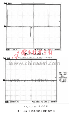
Figure 1 shows the transient response of the two A/V switch audio outputs, with the device periodically entering and exiting the shutdown mode. Depending on the design and internal structure of the amplifier, it may be necessary to monitor the transient response when the audio power is turned on and off.

As can be seen from Figure 1(a), the device generates a large amount of transient noise both when the power supply state changes and when the state of the device itself changes. For the MAX9598 (Figure 1(b)), the main source of transient noise is the dc offset drift at the output. This drift is only a few millivolts, so the transient amplitude remains within the oscilloscope's noise floor. For this reason, a more accurate measurement method needs to be sought.

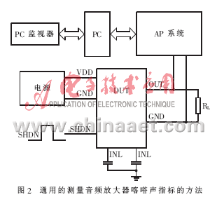
To achieve this, Maxim's audio group developed a common method to measure the click sound of different audio amplifiers (Figure 2), using the AudioPrecision (AP) System 1 and System 2 audio analyzers for measurements. Test the STV6412A and MAX9598 power supplies discussed above, with the input muted and the output connected to the AP.
The AP is set to record the peak voltage of the continuously monitored output. The device uses the device to test the maximum transient voltage of the AC-coupled STV6412A when it enters the standby mode and exits the standby mode and enters the operating mode, which are 244.1mV and -12.247dBV, respectively. The device also tested the maximum output transient voltage of the MAX9598. The device test conditions were transient conditions for entering and exiting standby mode, and transient conditions under power-on and off conditions. Table 1 summarizes the maximum values ​​of these measurements and compares the transient noise of the STV6412A with the MAX9598.
As can be seen from Table 1, the DC-coupled output can greatly suppress clicks. In addition, the ac coupling capacitor required for the STV6412A output is 1μF. Since such capacitance values ​​prevent low frequency components of the audio signal, most manufacturers require that the set-top box A/V switch use a capacitance of no less than 10μF. When the coupling capacitance is large, a larger voltage change may occur, resulting in a louder click.

Further analysis of AP measurements may reveal differences from oscilloscope measurements. These differences can be easily explained, and the AP input includes an A-weighted filter that filters out high-frequency noise and only preserves transient signals in the audio range. The oscilloscope measurement results include a more transient signal with bandwidth, and an A-weighted filter can be connected to the oscilloscope's probe for measurement. From the test results, the results obtained by the AP test system are more illustrative because it only displays the output signal of the audio range.
Table 1 provides a very objective test, but it still has subjective factors in terms of test results. Determining an acceptable or perceptible click level in a set top box is not an easy task. As mentioned earlier, these noises are also affected by other factors such as the volume of the TV, the efficiency of the speakers, and the distance between the speakers and the listener. However, it is obvious from the test results of this article that Maxim's DirectDrive technology can achieve a good click suppression effect.
This article discusses the click suppression in set-top boxes. One of the key factors is the ac-coupling capacitor at the audio output, and a way to eliminate this effect is proposed. Other ways to suppress click noise (such as controlling the power slew rate) improve system performance depending on the internal structure of the amplifier.
3 How to handle STB without SCART connector
For set-top boxes without SCART connectors, there is no need to switch audio and video signals too much, so the MAX9598 dual SCART audio/video switch is not a cost-effective option for any system. For this reason, the company also offers specific solutions for set-top boxes without SCART connectors. Set-top box designers typically use a single-supply dual op amp as the audio amplifier, the output is AC-coupled, and for video signals, separate devices are typically used.
For non-SCART systems, the MAX9597 provides a click-and-pop suppression method that is very close to the MAX9598. The MAX9597 supports filtering, amplification, and switching of 2Vrms audio signals from DC-coupled outputs for four video signal channels, accepting differential or single-ended signals from the set-top box audio CODEC.
APPDU intelligent power management project.Security is a set of professional intelligent power Management System, which can meet the requirements of UPS power supply, AC / DC power supply and Poe power supply, and can realize environmental monitoring and control (temperature, humidity, humidity, humidity) in the computer room. The fire alarm system can realize local and remote operation through centralized control software of power supply, monitor and control power consumption in real time .It can realize the function of building energy management . and develop software interface to any back-end cloud platform at the same time. In the real sense, the intelligent management of interconnection and interworking of power supply equipment in computer room has been realized.
Features:
High efficiency
Energy saving
safety
environment protection
Application:
It Widely used in banks, offices, buildings, office buildings, garden communities, squares, factories, prisons, road traffic, gas stations, ships and other machine room heavy, power failure self-lock, can be embedded in the back-end security system
Intelligent Management System(APPDU)
Intelligent Management System,Management System,Intelligent Blood Collection,Intelligent Management Fiber Optical
Dongguan Xiaoerduo Electronics Co., Ltd. , https://www.steadysmps.com