Application of LabVIEW in the production of the wiper motor of Volkswagen Bora A4 sedan
In the production of automotive wiper motor, how to test motor performance and motor vibration amount online, test data storage and barcode printing? Engineers use National Instruments' analog acquisition card and digital acquisition card with vibration sensor, magnetic powder brake, torque sensor, Encoders and controllable regulated power supplies have developed a reliable, economical and flexible PC-based motor test system.
This article refers to the address: http://
The Bora A4 sedan wiper motor produced by Volkswagen is a permanent magnet DC motor with a working voltage of 13V and a rated output of 40W. The motor leads are 4-wire, which are high-speed, low-speed, reset and ground. The wiper motor has its own gearbox. There is a switch inside the gearbox. When the reset terminal is connected with 13VDC voltage, the motor will rotate slowly. When the worm wheel bump reaches the reset point, the reset switch in the gearbox is closed and the motor armature is shorted. The motor consumes energy to brake, and the wiper is reset, and the power is disconnected.
According to the technical requirements of the project, it is necessary to test the high and low speed, high and low speed difference, high and low speed current, voltage and motor reset angle of the motor under certain load conditions, and stop the motor at the "loading angle", in addition to testing the motor. Vibration under no-load conditions.
Development software selection
After analyzing and comparing several excellent industrial control softwares in the world, Valeo's foreign technicians suggested that Shanghai Valeo Automotive Motor Wiper System Co., Ltd. use LabVIEW software to develop and manufacture special equipment. They think that "LabVIEW software" most excellent". According to the actual use of the production equipment of Shanghai Valeo Automotive Motor Wiper System Co., Ltd., the engineers demonstrated in LabVIEW, VB and other industrial control software, and finally chose LabVIEW software.
The main reason they chose LabVIEW software is that LabVIEW software programming is easy to learn, user friendly, powerful, stable, and short development cycle. In addition, because Shanghai Valeo Automotive Motor Wiper Systems Co., Ltd. previously used LabVIEW software to develop imported equipment, the engineers were trained in LabVIEW software, so engineers are familiar with the LabVIEW software system.
Selection board
The project requires a total of 4 analog inputs, 2 analog outputs, 2 counts, 7 digital inputs, and 12 digital outputs. Select NI's analog capture card PCI-6024 board, which has 8 differential analog inputs, 2 analog outputs, sampling rate of 200KS / s, 12bits, 2 way count, 8 digital I / O end.
The other board is the digital capture card PCI-6503: it has 24 I/O terminals.
Overall design
â–¡ The engineers first opened several text files in the C drive. The files contained the upper and lower limits of the motor performance parameters such as voltage, current, and speed; the upper and lower limits of the motor vibration parameter; the adjustment factor of the vibration sensor; The nonlinear adjustment coefficient of the magnetic powder brake. Each time the program is run, the data in the above text files is read first as an indicator and test coefficient for judging whether the motor is good or bad. The advantage of this is that these key parameters can only be modified by the relevant engineers, and the operator can not be modified to avoid human error. (The motor test interface is shown in Figure 1.)
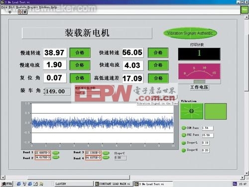
Figure 1 Motor performance and vibration test interface
â–¡ In order to ensure the correctness of the test motor terminal voltage, two feedback lines are added to the motor end, which are automatically adjusted by the regulated power supply. The regulated power supply also selects a controllable type, that is, the analog acquisition card outputs a variable signal of 0 to 5V to control the output of the regulated power supply. This ensures the correctness of the test motor terminal voltage and program controllability.
â–¡ The magnetic powder brake also selects a controllable regulated power supply. Different test torques select different operating voltages. Because the magnetic powder brake is a non-linear component, in order to ensure the correctness of the test torque, the engineers installed a calibrated torque sensor under the rotating disk of the motor test end and designed the calibration procedure.
The adjustment method is as follows: first install a lever on the motor rotation test end, hang the 500g weight on one end of the lever, and read the electrical signal of the torque sensor as the standard of the point. Then, different weights such as 1000g, 1500g, and 2000g are sequentially suspended to read electrical signals at different points.
Take the lever and the weight, install a motor to be tested on the test fixture and energize it to rotate, and then gradually increase the input voltage of the magnetic powder brake. At this time, the output electrical signal on the torque sensor is gradually increased. When the electrical signal values ​​of the above different weight output points are recorded, the input voltages of the magnetic powder brakes are recorded separately. These voltages are the load voltages at these points, and then the K and B values ​​between the adjacent two points are calculated according to the binary one-time equation. , the approximate load working voltage value of the magnetic powder brake at any point can be obtained.
â–¡ The encoder for speed test uses PEPPERL+FUCHS products with a resolution of 2500 pulses per revolution. The two counting ends of the analog capture card 6024 are used to measure the rotational speed of the motor under test and the angle of the motor rotation. This work has been done in the LabVIEW software example and can be used as long as it is copied.
â–¡ The current signal sampling uses 30A/75mV 0.2-level current shunt, and then through the current transmitter, it becomes 0~5V voltage and is sent to the analog input end of the acquisition card.
â–¡ The voltage signal is sampled by 0~30V/0~5V voltage signal isolator, and the voltage of 0~5V is sent to the analog input end of the acquisition card.
â–¡ Vibration measurement uses the accelerometer and amplifier of the PCB. The measuring bag is placed down for each measurement. The magnet on the sensor is sucked on the motor casing for measurement. The vibration signal is analyzed by “Hanning window†and “spectrumâ€. The vibration waveform is output after processing. It is divided into four frequency bands in the frequency range of 10~4500Hz, and the vibration quantity of each frequency band is set with different upper and lower limits to find different defects of the motor.
At the same time, a group of motor vibration signals are continuously measured, and the time domain is used for identification analysis. CGM (Case Growl Measurement): It is used to identify the waveform of the pulse signal of the motor rotor during the rotation period. It can measure the maximum and minimum values ​​of the vibration signal of the rotor of the motor in one revolution. It can find many motor defects, such as worm teeth, commutator defects, and worms with scratches in the bearing gear. PRI (Pulse Ratio Index): It can be found that the two points on the shaft are out of tolerance, the shaft is bent, and the surface of the commutator is flawed.
Different motor products and different test methods have different vibration waveforms. Only after accumulating a large amount of empirical data can the motor's vibration waveform be correctly judged based on the motor vibration waveform.
LabVIEW software has a strong advantage in vibration measurement and noise measurement. NI provides vibration and noise measurement software packages, and users can make their own applications by making minor changes according to their actual situation.
â–¡ In order to ensure the accuracy of the vibration test, the acceleration sensor and amplifier should be calibrated regularly. When adjusting, enter the vibration adjustment program, apply vibration to the sensor with a standard vibration source of 159.2Hz 1g (9.8m/s2), and read the amplifier signal to see if it reaches 1g, and correct it, and save the correction coefficient into the text. File to call correction when testing the motor.
â–¡ Storage of test data: During the test, because one motor is vibrated at the same time and the other motor is tested for performance, two different files are used for data storage. The date is the file name and is stored in the EXCEL file. The key here is to correctly determine the serial number of the motor.
□ Barcode printing: After all the tests of the motor are qualified, it is printed by a “zebra†barcode printer. The barcode is recorded on the product model, serial number, date, etc. The serial number is consistent with the test serial number of the motor in the storage file. Thereby achieving product traceability.
□ In practical applications, how to quickly detect equipment failures is a common problem. In order to perform equipment fault detection more conveniently and intuitively, you can enter the fault detection subroutine by selecting the “Fault Detection†button on the main panel. The analog, digital I/O and count terminals used by the device are placed on the panel of the program. (Figure 2)
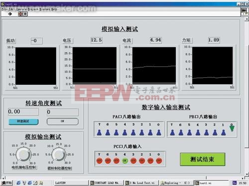
Figure 2 device fault detection test interface
â–¡ The analog input signal selects the oscilloscope display mode, the analog output signal selects the knob to control the output mode, the digital input signal selects the indicator display mode, the digital output signal selects the switch control output mode, the count signal selects the button and the digital display mode.
This is very intuitive. Any action of the output knob and button will cause the action of the electrical components connected to the corresponding output. At the same time, any changes in the switch and electrical signals connected to the periphery will be displayed on the screen. This is very convenient for equipment maintenance, but it is important to note that safety must be observed in specific applications. Because some electrical appliances, such as: motors, cylinders, etc., must be operated under certain conditions, otherwise accidents are likely to occur, so it is necessary to impose certain restrictions on the application.
Conclusion:
The project of Shanghai Valeo Automotive Motor Wiper System Co., Ltd. has been successfully completed after more than one month of development. It has been put into normal production and use, and the equipment is running very stable. Through this successful application, engineers at Shanghai Valeo Automotive Motor Wiper System Co., Ltd. have accumulated experience in production and improved confidence in developing and developing more specialized test and production equipment using LabVIEW software.
Runway Speaker,Runway Micro Speaker,Track Runway Speaker,Outdoor Runway Speakers
NINGBO SANCO ELECTRONICS CO., LTD. , https://www.sancobuzzer.com