Car digital camera charging adapter design
The drawing shows a digital camera charging adapter circuit. The circuit uses a pair of transistor differential amplifiers and a primary current amplifier. A constant voltage and a required current are respectively output. Transistors T1 and T2 form a pair of differential amplifiers. The base voltage of T1 is stabilized at 3V by Zener diode ZD1. The T2 base voltage is obtained by dividing the Power Supply through R3 and R4. T1 and T2 compare the base voltage with each other and adjust the base current of current amplifier T3 accordingly.
This article refers to the address: http://
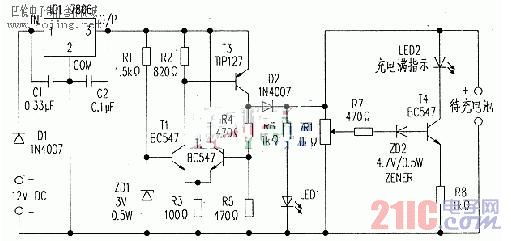
Transistor T3 is connected to a current amplifier to provide sufficient current for charging. T3 uses TIP127. It is a medium power Darlington transistor with a current amplification factor of 1000. Therefore, if the T3 base current is 1 mA, the collector current will be 1A at maximum. T3 is connected to the inverting amplifier mode of operation. Therefore, when a positive voltage is applied to the base of T1, T1 will output a negative pulse to drive T3. R2 provides a current of about 1 mA for the base of T3. Therefore the T3 collector will output 1A.
The 100Ω R3 plays a major role in the process of regulating the output voltage and current by the differential amplifier. The current through R3 is the sum of the emitter currents of T1 and T2. The collector current of the T2 collector is fixed due to the direct connection of the 6V power supply.
Therefore, the T3 base current varies with the magnitude of the current flowing through R2 and R3. This design stabilizes the charging voltage and current. Any change in the output voltage is detected by transistors T1 and T2, and the base current of T3 is adjusted accordingly.
The adapter's power supply is obtained from the 12v car battery via the cigarette lighter socket. The regulator 7806 (IC1) reduces the 12V input voltage to 6V and limits the output current to 1A.
The bypass capacitors C1 and C2 are connected to the pins of Ic1 during soldering. Ic1 must be equipped with a suitable heat sink to dissipate heat.
LED1 and LED2 are used to indicate "charging" and "charging is full", respectively. When the digital camera is connected to the adapter, LED1 illuminates to indicate "charging" and LED2 remains off. The 4.7V Zener diode ZD2 acts as a diode switch that drives T4 into a conducting state only when the battery terminal voltage exceeds 5.3v (=4.7v+0.6v), causing LED2 to illuminate, indicating "charging is full." Whether the rechargeable battery reaches 5.3v can be adjusted with VR1. D1 and D2 in the figure are used for polarity protection.
The circuit can be mounted on a common PCB board. And put it into the appropriate box. Plug the plug of a car phone charger into the cigarette lighter socket in the car.
All 18.5V laptop adapters are 100% brand new, and for the main brand laptop such as HP, Dell and so on. all the laptop chargers have over voltage protection, over temperature protection, short circuit protection, and all the laptop adapters are 100% aging test before shipment. Anyway, if you still worry about the quality, you also can place an Assurance Order in Alibaba, you will get 100% full refund if bad quality or delay delivery. This service is designed by Alibaba to create trust for trade.
18.5V Laptop Adapter,18.5V Ac Laptop Adapter,Dc Laptop Adapter,18.5V Laptop Power Adapter
Shenzhen Pengchu Industry Co., Ltd , https://www.pc-adapters.com