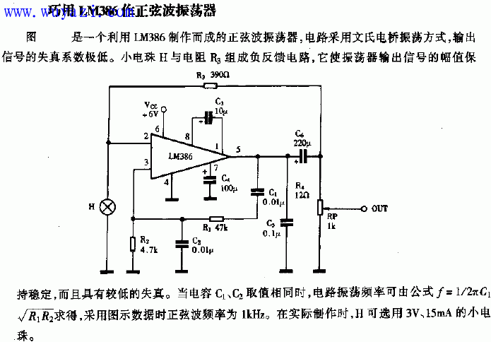
RC sine wave oscillation circuit diagram
RC sine wave oscillation circuit diagram:

The RC sine wave oscillation circuit is a common type of oscillator, often referred to as the Wien bridge oscillator. It uses an RC series-parallel network as both a frequency-selective and feedback component. Here's a detailed explanation of its operation:

The series-parallel network functions as a frequency-selective element, ensuring that only a specific frequency can sustain oscillation. The basic configuration is shown in the figure above.
The starting condition for oscillation is given by the formula:

This ensures that the loop gain is sufficient to start oscillations.
The oscillation frequency of the RC bridge oscillator is determined by:

This makes it ideal for low-frequency applications. For higher frequencies, LC oscillators are typically used instead, with their own frequency formula:

Quartz oscillators, on the other hand, are known for their high frequency stability, making them suitable for applications where precise timing is essential.
Another version of the RC sine wave circuit is shown below:


When R1 = R2 = R and C1 = C2 = C, the frequency response becomes more predictable, leading to a stable output.
The amplitude and phase characteristics of the RC network are crucial for determining the behavior of the oscillator. At the resonant frequency fâ‚€, the amplitude reaches its peak, and the phase shift is zero, allowing for sustained oscillations.
For the RC bridge oscillator, the circuit includes an operational amplifier with a feedback network formed by the RC series-parallel network. This setup allows for precise control over the oscillation frequency and amplitude. The negative feedback helps stabilize the output, while the positive feedback ensures that the oscillation starts and continues.
The stabilization process involves using a thermistor (Rf) to regulate the gain of the amplifier. As the output voltage increases, the thermistor heats up, reducing its resistance and thus lowering the gain. This prevents the signal from becoming too large and distorting.
When the circuit is first powered on, the thermistor is cold and has a high resistance, allowing the amplifier to have a higher gain. As the signal builds up, the thermistor warms, reducing its resistance and stabilizing the output. This dynamic adjustment ensures that the oscillator runs smoothly without distortion.
An example of such a circuit includes components like R1 = 6.2kΩ, Rp = 22kΩ, R3 = 4.3kΩ, R = 8.2kΩ, and C = 0.01μF. These values determine the frequency and stability of the output signal.
Special Material Braided Sleeve
Special Material Braided Sleeve,Heat Proof Sleeve,Heat Proof Wire Sleeve,High Temperature Cable Sleeving
Shenzhen Huiyunhai Tech.Co., Ltd. , https://www.cablesleevefactory.com