LLC technology has become increasingly popular and is not expected to fall behind in the future! The half-bridge LLC resonant circuit can be configured in different ways based on the resonant capacitor. Typically, there are two common configurations, as shown in Figure 1. The main difference lies in how the resonant cavity is connected. In the left configuration, a single resonant capacitor (Cr) is used. This setup results in higher input current ripple and RMS values but offers simpler wiring and lower cost. On the right, a split resonant capacitor (C1 and C2) is used instead. This reduces input current ripple and RMS current, with only half of the current flowing through each capacitor, thus requiring less capacitance overall.
The basic principle of the LLC half-bridge resonant circuit involves DC characteristics that operate in either a zero voltage or zero current region. There are two resonant frequencies: one from the Lr and Cr series resonance, and another involving Lm, Cr, and the load. As the load increases, the resonant frequency also rises. The formulas for calculating these frequencies are provided below:

To maximize efficiency, the operating frequency should be set near fr1, which is the resonant frequency of the Lr and Cr series circuit. When the input voltage drops, reducing the operating frequency allows for a larger gain. By carefully selecting the resonant parameters, the LLC converter can maintain zero voltage switching regardless of load or input voltage variations.
In general, the switching behavior of the LLC half-bridge resonant circuit is similar to a standard half-bridge, but due to the addition of the resonant tank, the upper and lower MOSFETs operate differently. This enables zero-voltage turn-on, resulting in reduced switching losses. The working waveform is illustrated below:
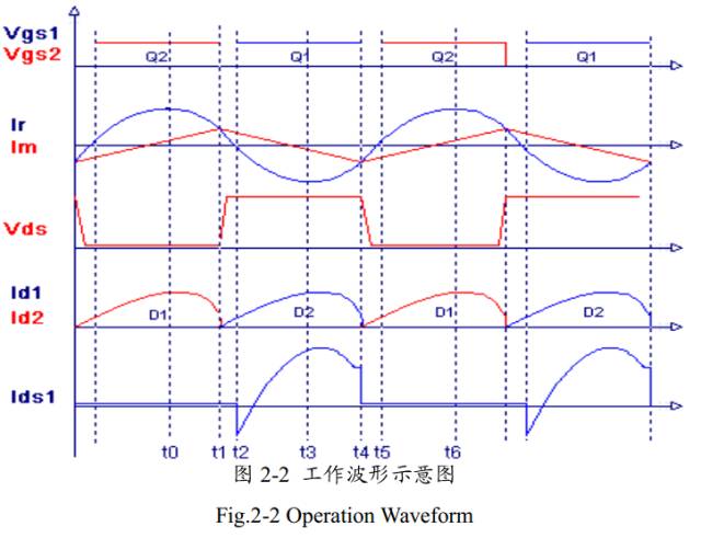
This waveform shows the operation of an ideal half-bridge resonant circuit, where Vgs1 and Vgs2 represent the gate voltages of Q1 and Q2, respectively. Ir represents the current through the resonant inductor Lr, Im is the current through the transformer leakage inductance Lm, and Id1 and Id2 are the currents through the secondary-side rectifier diodes. The waveform is divided into six distinct stages, each representing a different operational state of the circuit.
**T0–T1**: Q1 is turned off, and Q2 is turned on. The resonant inductor current is negative, flowing through Q2. During this phase, the transformer leakage inductance does not participate in the resonance, and energy is supplied by Cr and Lr. The phase ends when Q2 turns off.
**T1–T2**: Both Q1 and Q2 are turned off, creating a dead time in the half-bridge. The resonant inductor current remains negative, discharging Q1’s output capacitance (Coss) and charging Q2’s Coss until it matches the input voltage, preparing for zero-voltage turn-on of Q1. The transformer secondary is isolated from the primary during this phase.
**T2–T3**: Q1 turns on, and Q2 turns off. The resonant inductor current continues to flow back to the input through Q1’s body diode. D1 is forward-biased, delivering power to the output. This phase ends when the resonant inductor current reaches zero.
**T3–T4**: The resonant inductor current changes direction, and the same conditions as T2–T3 apply. Lr and Cr continue to resonate, while Lm is charged. This phase ends when Q1 turns off.
**T4–T5**: Both Q1 and Q2 are off again. The resonant inductor charges Q1’s Coss and discharges Q2’s Coss, allowing for zero-voltage turn-on of Q2. The transformer secondary is once again isolated from the primary.
**T5–T6**: Q2 turns on at zero voltage, and the resonant inductor freewheels through Q2. D2 supplies the output, and the cycle repeats.
From the above analysis, it's clear that the circuit operates primarily at a high resonant frequency composed of Lr and Cr, except during the dead times. The transformer’s leakage inductance is clamped by the output voltage, behaving like a passive load. This means it doesn’t fully participate in the resonance process. As a result, LLC converters may struggle to achieve very high frequencies under light loads. However, this passive nature ensures reliable zero-voltage switching across all load conditions.
Temperature And Humidity Test Chamber
Temperature And Humidity Test Chamber,Temperature Humidity Test Box,Test Machine For Aerospace,Constant Temperature Humidity Tester
Wuxi Juxingyao Trading Co., Ltd , https://www.juxingyao.com