RC sine wave oscillation circuit diagram
RC sine wave oscillation circuit diagram: 
The RC sine wave oscillation circuit is one of the most common types used for generating low-frequency sinusoidal signals. It is also known as the Wien bridge oscillator, which uses an RC series-parallel network as a frequency-selective and feedback component. This circuit is particularly useful in applications where stable and clean sine waves are needed at lower frequencies. 
In this configuration, the series-parallel network serves both as a frequency selector and a feedback mechanism. The basic structure is shown in Figure (1), and the starting condition for oscillation can be expressed as:
The oscillation frequency is given by the formula:
This type of circuit is typically used for frequencies ranging from 1 Hz to 1 MHz. For higher frequency sine wave generation, an LC oscillator is generally preferred, as it can provide better stability and performance at higher frequencies. The oscillation frequency for an LC oscillator is given by:
Quartz oscillators, on the other hand, are known for their high frequency stability. They are widely used in applications where precise and consistent frequency output is required, such as in communication systems, timing circuits, and precision instruments.
Another example of an RC sine wave circuit is shown below. This type of circuit, composed of an RC frequency-selective network, is commonly used for generating low-frequency signals. The two main types of RC oscillators are the RC bridge oscillator and the RC phase shift oscillator. In this section, we will focus specifically on the RC bridge oscillator, which uses a series-parallel RC network for frequency selection.
The frequency response of the RC series-parallel network is crucial for understanding how the circuit operates. The impedance of the series arm is denoted as Z1, while the impedance of the parallel arm is denoted as Z2. Their frequency response can be described as follows:

When R1 = R2 = R and C1 = C2 = C, the frequency characteristics simplify, and the amplitude and phase responses become more predictable. The amplitude and frequency characteristics are given by:
The phase frequency characteristics are also important for determining the conditions under which the circuit will oscillate. These are illustrated in the following figures:

As seen from the graphs, when the frequency reaches the resonant frequency f0, the amplitude of the output voltage reaches its maximum value of 1/3, and the phase shift is zero. This means that the output signal is in phase with the input, making it ideal for sustained oscillations. This behavior confirms that the RC series-parallel network has a clear frequency selection function.
The RC bridge oscillator circuit is designed to take advantage of this property. It consists of an operational amplifier, along with an RC series-parallel network connected between the output and non-inverting input terminals. This forms a positive feedback loop with frequency selection. Additionally, a negative feedback network is created using resistors Rf and R1, which helps stabilize the gain and control the amplitude of the output signal.
As shown in the figure, the positive and negative feedback loops form what is known as a Wien bridge. The operational amplifier’s input and output are connected across the diagonal of the bridge, giving the circuit its name. The configuration ensures that only the desired frequency is amplified and sustained, leading to stable sine wave output.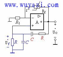
For the negative feedback amplifying circuit, the input signal is applied to the non-inverting terminal, and the closed-loop voltage gain can be calculated based on the virtual short and virtual open concepts. The formula for the gain is:
At the resonant frequency f0, the amplitude start condition is satisfied when:
The phase start condition requires that the total phase shift around the loop is zero, ensuring sustained oscillation. This is achieved through the design of the RC network and the feedback arrangement.
The amplitude stabilization in the RC bridge oscillator is primarily handled by a thermistor, usually placed in the feedback resistor Rf. This thermistor has a negative temperature coefficient, meaning that as the output voltage increases, the resistance decreases, thereby increasing the negative feedback and reducing the amplitude of the output. This self-regulating mechanism ensures that the output remains stable without distortion.
If the resistor RF is a fixed value, the amplifier gain Au remains constant. However, during startup, the condition must satisfy:
Once oscillation is established, the balance condition requires:
Only when the operational amplifier enters the nonlinear region can the gain drop to a level that allows for stable oscillation, but this may result in some distortion if not properly controlled.
In contrast, when RF is a negative temperature coefficient thermistor, the system behaves differently. During startup, the signal is weak, so the thermistor is cold and has a higher resistance, allowing the amplifier to have a higher gain. As the signal builds up, the thermistor heats up, its resistance decreases, and the amplifier gain automatically reduces until equilibrium is reached. This process ensures a smooth and stable oscillation without excessive distortion.
An example of an RC bridge oscillator circuit includes the following parameters: R1 = 6.2 kΩ, Rp = 22 kΩ, R3 = 4.3 kΩ, R = 8.2 kΩ, and C = 0.01 μF. These values are chosen to achieve the desired frequency and stability in the circuit.
Braided Sleeve,Braided Cable Sleeve,Expandable Braided Sleeving,Braided Wire Sleeve
Shenzhen Huiyunhai Tech.Co., Ltd. , https://www.cablesleevefactory.com