Phone network alarm system connector circuit design
Telephone network alarms are widely used because of their quick and effective advantages. The Universal Serial Bus USB, which has gradually become the mainstream interface of computers, is well adapted to the expansion of multimedia functions of modern computers. At present, the interface of the universal alarm platform is expensive with a PCI card, and cannot be plug and play. The use of a USB interface instead of a PCI card not only reduces costs, but also improves the ease of use and maintainability of the management platform. The main function of the cell alarm management platform implemented in VC++ is to receive the alarm information transmitted from the user alarm system through the telephone network, and then send the alarm information to the monitoring host through the USB interface, and pre-stored in ADO (AcTIvex Data Objects). The user information of the database is searched to determine specific user information, so as to timely handle the police in the community. The system is mainly composed of a pre-processing circuit that receives alarm information and a PC (see Figure 1). The alarm information receiving pre-processing circuit receives the alarm information transmitted from the telephone network, formats the alarm information, and transmits the information to the PC through the USB interface. The PC receives the formatted information sent back, performs information analysis and error processing, confirms the correct format, and then compares with the user data in the database (ADO), and pops up the information of the alarm user through the alarm dialog box.
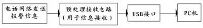
Figure 1 System block diagram
System hardware
The front-end circuit is mainly composed of HT9032 (FSK demodulation circuit), single-chip AT89C81, analog pick-up circuit, line abnormality monitoring circuit and EZ-USB FX2 (CY7C68013) (USB interface circuit), as shown in Figure 2. The HT9032 is an FSK decoder chip with pin and function compatible with Freescale's MC145447 and EMC's EM92547A. Figure 3 shows its peripheral circuitry and its connection to the microcontroller.
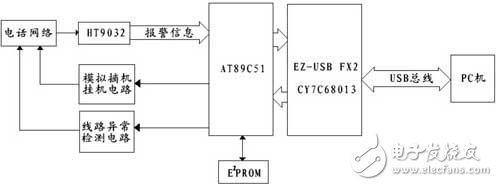
Figure 2 front-end circuit of the system
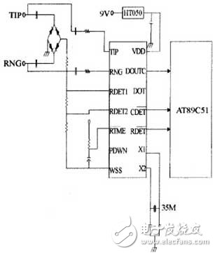
Figure 3 HT9032 circuit connection diagram
The DC and AC voltages on the telephone line are higher than the voltage of the alarm host. An optocoupler needs to be added at the interface to isolate the power of the program-controlled switch and the alarm. It is necessary to avoid an outdoor disconnection or an outdoor illegal parallel, and the alarm is not detected when the alarm is off-hook. An abnormality occurs, the optocoupler is turned on, and the collector outputs a low level to the microcontroller to perform an abnormal alarm interrupt processing. The PNP triode is used to control the opening and opening of the normally open end of the relay. When the MCU sends the off-hook signal, the base of the triode is low, the triode is turned on, the relay is closed, and the resistance across the telephone line is reduced to about 300 nΩ, thus enabling analog off-hook. When the MCU sends an on-hook signal, the base of the triode is at a high level, the triode is turned off, the normally open end of the relay is turned on, and the resistance rises to infinity, thereby implementing analog hung.
Household Electrical Appliances
gree , https://www.greegroups.com