Circuit Design Analysis of Single Chip Microcomputer System - Circuit Diagram Reading Every Day (277)
The following describes the minimum system circuit design of the MCU. The minimum system of the MCU is mainly composed of the power supply, reset, oscillation circuit and extension. For a complete electronic design, the first problem is to provide power supply modules for the entire system. The stability and reliability of the power modules is the premise and basis for the smooth operation of the system.
1, the power supply
When using STC89C52RC MCU, the working voltage: 5.5V-3.4V (5V MCU), this place shows that the normal working voltage of our MCU is a range value, as long as the power supply VCC is working between 5.5V and 3.4V. If the voltage exceeds 5.5V, it is absolutely not allowed. It will burn out the MCU. If the voltage is lower than 3.4V, the MCU will not be damaged, but it will not work properly.
2, the oscillation circuit
There is a crystal oscillator in the single-chip system. In the single-chip system, the crystal oscillator is very large. The whole process is called crystal oscillator. He combines the internal circuit of the single-chip microcomputer to generate the clock frequency required by the single-chip microcomputer. The higher the clock frequency provided by the single-chip crystal oscillator, the higher the running speed of the single-chip microcomputer. Fast, single-chip execution of all instructions is based on the clock frequency provided by the microcontroller crystal.

Crystal oscillator
The crystal oscillator is usually divided into two types: a passive crystal oscillator and an active crystal oscillator. A passive crystal oscillator is generally called crystal, and an active crystal oscillator is called an oscillator.
The active crystal oscillator is a complete resonant oscillator. It uses the piezoelectric effect of the quartz crystal to start the vibration. Therefore, the active crystal oscillator needs to be powered. When we do the active crystal oscillator circuit, it does not need an external circuit. The oscillation frequency is actively generated, and a high-precision frequency reference can be provided, and the signal quality is better than that of the passive signal.
Active crystals typically have four pins, VCC, GND, a crystal output pin, and an unused floating pin. The passive crystal oscillator has 2 or 3 pins. If it is 3 pins, the middle pin is the crystal oscillator case. When it is used, it should be connected to GND. The pins on both sides are the two lead pins of the crystal. The two pins function the same, just like the two pins of the resistor, there is no positive or negative. For the passive crystal oscillator, it is connected with the two crystal oscillator pins on our single-chip microcomputer, and the active crystal oscillator is only connected to the input pin of the crystal oscillator of the single-chip microcomputer, and the output pin does not need to be connected, as shown in Fig. 1. And Figure 2 shows.
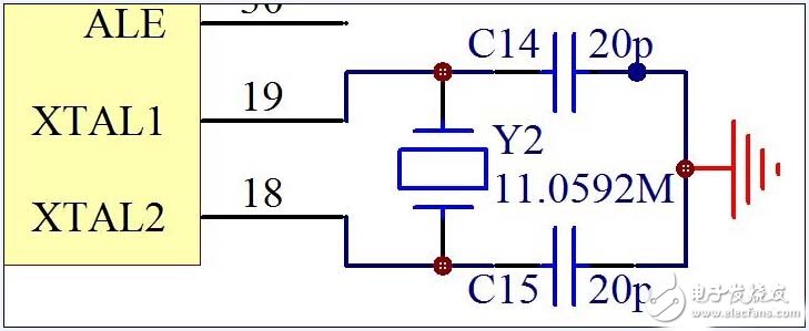
Figure 1 Passive crystal connection
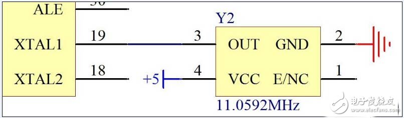
Figure 2 Active crystal connection
3, reset circuit
Let's first analyze our reset circuit, as shown in Figure 3.
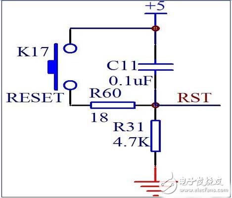
Figure 3 microcontroller reset circuit
When the circuit is in a steady state, the capacitor acts to isolate the DC, and the +5V is isolated, and the reset button on the left side is in the pop-up state, and the lower part of the circuit has no voltage difference, so the button and the capacitor C11 are below. The potential is equal to GND, which is 0V. Our single-chip microcomputer is a high-level reset, low-level normal operation, so the normal working voltage is 0V voltage, completely OK, no problem.
4, independent button
The usual buttons are divided into two types: free-standing buttons and matrix buttons. The stand-alone buttons are relatively simple and connected to separate input lines, as shown in Figure 4.
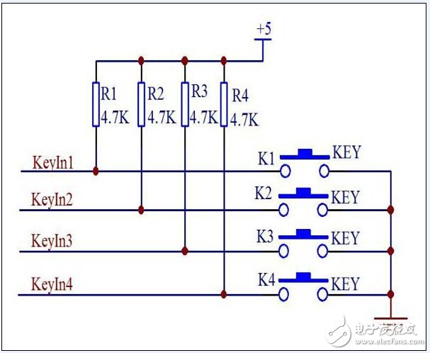
Figure 4 free-standing button circuit diagram
Portable power supply
Portable power station
Rechargeable Emergency power supply for outdoors
Quick charge power station for power tools
Yacht Batteries,Portable power supply, Rechargeable Power station
Shenzhen Sunbeam New Energy Co., Ltd , https://www.sunbeambattery.com