Mouse lower shell modeling and mold design process
This is an article that combines the introduction of mouse products with Pro/ENGINEER software to complete product modeling and mold design.
This article refers to the address: http://
First, Pro/ENGINEER product and mold design process
Pro/ENGINEER mainly includes CAID (industrial design), CAD (mechanical design), CAE (functional simulation), CAM (manufacturing), PDM (data management) and Ge-ometry Translator (data exchange) modules. In the product and mold design, generally follow the following process.
1. Three-dimensional modeling
The 3D model of the part is drawn using the Part module based on the 2D sketch of the part.
2. Mold design
According to the provided three-dimensional model, the CM module is used to complete the mold design of the part.
3. Mouse 3D modeling
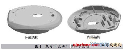
Use the Extrude, Pattern, Sweep, Hole, and Draft commands provided by the Pro/ENGINEER software Part module to create a mouse under the mouse as shown in Figure 1. Shell model.
Second, the core and cavity design of the mouse lower shell mold
1. Structure of the workpiece
The outer surface structure of the workpiece is relatively simple, and there is a through hole and a blind hole. It is conceivable to create a small core at the through hole; the internal structure of the workpiece is complicated, except for one blind hole, a small core needs to be designed, and the rest are The support structure of the circuit board is not large in thickness and height direction, so the integral core can be considered and processed by means of electric spark.
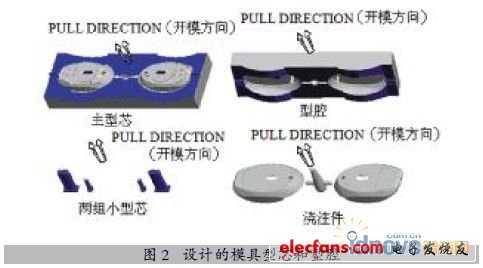
2. Gating system
For mouse shell parts, the gate should not be opened on the outer surface to avoid affecting the appearance. Generally, it should be opened inside (latent gate) or edge of the part (side gate). Due to the complicated internal structure of the workpiece, the gate is opened at the edge of the workpiece, and a two-cavity or four-chamber arrangement is adopted to balance the flow path. as shown in picture 2.
This is an article that combines the introduction of mouse products with Pro/ENGINEER software to complete product modeling and mold design.
First, Pro/ENGINEER product and mold design process
Pro/ENGINEER mainly includes CAID (industrial design), CAD (mechanical design), CAE (functional simulation), CAM (manufacturing), PDM (data management) and Ge-ometry Translator (data exchange) modules. In the product and mold design, generally follow the following process.
1. Three-dimensional modeling
The 3D model of the part is drawn using the Part module based on the 2D sketch of the part.
2. Mold design
According to the provided three-dimensional model, the CM module is used to complete the mold design of the part.
3. Mouse 3D modeling
Use the Extrude, Pattern, Sweep, Hole, and Draft commands provided by the Pro/ENGINEER software Part module to create a mouse under the mouse as shown in Figure 1. Shell model.
Second, the core and cavity design of the mouse lower shell mold
1. Structure of the workpiece
The outer surface structure of the workpiece is relatively simple, and there is a through hole and a blind hole. It is conceivable to create a small core at the through hole; the internal structure of the workpiece is complicated, except for one blind hole, a small core needs to be designed, and the rest are The support structure of the circuit board is not large in thickness and height direction, so the integral core can be considered and processed by means of electric spark.
2. Gating system
For mouse shell parts, the gate should not be opened on the outer surface to avoid affecting the appearance. Generally, it should be opened inside (latent gate) or edge of the part (side gate). Due to the complicated internal structure of the workpiece, the gate is opened at the edge of the workpiece, and a two-cavity or four-chamber arrangement is adopted to balance the flow path. as shown in picture 2.
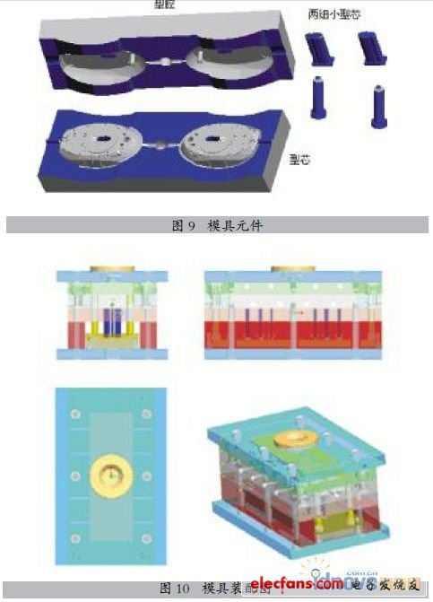
6. Split the mold volume
Firstly, the workpiece is divided by the slider type to obtain the sliders of each group; and the front and rear modes are obtained by dividing the workpiece volume block which is left after the segmentation of the slider by the main part type. Go to “Mold Volume†→ “Split†→ “TowVolume†→ “Workpiece†→ select the volume to be divided → “Pick†→ select the parting surface → define each volume, use the reference part model and the mold volume for Boolean subtraction The operation acquires the cavity. Enter “Mold Comp†→ “Ex-tract†to complete the mold volume extraction, as shown in Figure 9.
7. Create a model
Go to “Molding†→ “Create†and simulate the casting.
8. Generate mold assembly drawing
Adding the mold base, creating the water line, modifying the ejector rod, modifying the fixing plate and the spacer block, eliminating the masking of each part, the assembly drawing of the designed mold can be seen, and the design of the entire mold is completed. The result is shown in Figure 10.
Antenk Box Header Connector,Those products are used in more or less every known application within computer-, industrial-, telecommunication and specific automotive markets. This product technology allows cost effective connections between printed circuit boards based on removable or permanent connections based on a longterm proofed way of assembly. Box Header connectors are available with the traditionally used pitch of 2.54mm and the pitch of 2.00mm,1.27mm.
Antenk Box header/Ejector Header Description and Application:
Box header/ ejector header connector, With DIP straight/vertical, SMT,Right angle, 2.54pitch, 2.0pitch, 1.27pitch,
The commonly used Pin ways have 6P,8P,10P,14P,16P,20P, 24P,26P,30P,34P, 40P,50P,64P.
Box header/ ejector header and IDC flat cable connectors are two of the most commonly used connectors. Box headers can be found in nearly all electronic equipments.
This is a IDC product which allows cost effective connections between circuit boards based on permanent connection (using transition connector) or removable connection
(Using for IDC flat cable connectors).
Box header

Ejector header

Box Header Connector
Box Header,Box Header Connector,Ecu Box Header Connector,Latch Box Header Connector,1.27mm Box Header Connector,2.00mm Box Header Connector,2.54mm Box Header Connector
ShenZhen Antenk Electronics Co,Ltd , https://www.antenk.com