IR2104 chip driver circuit realizes smart car differential control scheme
Because I mainly engage in software, so the hardware is not very well understood, but in order to better learn from each other, only a summary of this, and what is wrong, please please actively point out! For everyone to study together!
The smart car we are doing, in order to complete a game well, requires excellent control strategy! As far as the whole smart car system is concerned, our controlled object is nothing more than the steering gear and the motor! Through the steering gear Control allows our car to correct the position of the car on the track in real time and complete the steering! Of course, those who do the same balance group as me do not have to consider the problem of the steering gear! The motor is the power guarantee for the car to complete the game, while the balance group Students also need to control the direction of the car by differential control of the two-way motor! So it is necessary to choose a good motor drive circuit!
There are two ways to drive the motor in common: first, using an integrated motor to drive the chip; second, using a MOSFET and a dedicated gate driver chip. The integration is mainly Freescale's own 33886 chip, and the L298 chip, of which 298 is a good chip, its internal can be seen as two H-bridge, can drive two motors at the same time, and it is also our drive stepping A good choice for the motor! Because their drive current is small (33886 maximum 5A continuous work, 298 maximum 2A continuous work), it is not enough for our smart car, but it may be used in the electronic design competition! So I want to To learn more about their classmates, you can find their data sheets! Here are just their circuit diagrams, not to be detailed!

33886 application circuit diagram
The following highlights the drive circuits that our smart cars may use. Commonly used is Infineon's half-bridge driver chip BTS7960 to form a full-bridge driver. Its drive current is about 43A, and its upgraded product BTS7970 drive current can reach 70 amps! And there is also its alternative product BTN7970, its drive current can reach up to 70 amps! Its internal structure is basically the same as follows:

There are two MOS transistors inside each chip. When the IN input is high, the upper MOS transistor is turned on. It is often called the high-side MOS transistor. When the IN input is low, the lower MOS transistor is turned on, which is often called low. Side MOS tube; when INH is high, the whole chip is enabled, and the chip works; when INH is low, the chip does not work. The typical application circuit diagram is shown below:
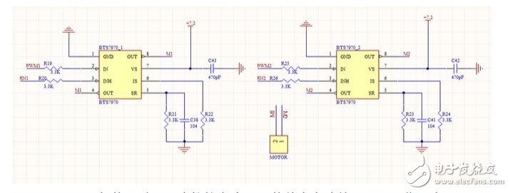
When EN1 and EN2 are generally used, we directly connect to the high level, so that the entire circuit is always working!
The following is how to use this circuit to make the motor forward and reverse? If PWM1 input PWM wave, PWM2 terminal is set to 0, the motor is rotating forward; then when PWM1 terminal is 0, PWM2 terminal input PWM wave, the motor will reverse! Use this The method requires two PWM signals to control one motor. The students of the photoelectric balance group need 4 channels! It is a waste! In fact, only one PWM can be used to connect to the PWM1 terminal, and the PWM2 terminal can be connected to the IO port for controlling the direction! If PWM2=0; when the PWM1 input signal, the motor rotates forward, then when PWM2=1, the PWM1 input signal motor reverses (must note: the PWM signal input is its corresponding negative duty cycle)!
For the above circuit, this year's electromagnetic group A car and photoelectric group D car, its driving current can be satisfied, but for this year's camera group B car model, it may be a little hard, B car motor power is very large, Although the current during normal forward rotation is not very large, when we add our speed control strategy, many times the car is constantly accelerating and decelerating, which requires the motor to continuously reversing, the current at this time Very large, also use the above drive circuit, the chip will be very hot!! This time we need to use our own MOSFET and gate drive chip to design the H-bridge!
First, let's briefly introduce the basic principles with the circuit diagrams on the driver board that the school provides to everyone:
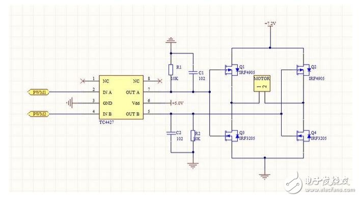
The first thing we need to understand is that the TC4427 is a 1.5A dual-channel high-speed MOSFET driver. As its name implies, it has two in-phase driver circuits A and B inside.
In the above circuit, 4905 is a P-channel, and 3205 is an N-channel. Everyone has learned a few electric modes, even if they have not learned their conduction conditions, it is assumed that PWM2=0, that is, Q2 is turned on. Q4 is not conducting! Then when PWM1=1, Q1 is not turned on, Q3 is turned on, the direction of current is Q2—motor—Q3, the motor is rotating forward. When PWM1=0, Q1 is turned on, and Q3 is not turned on. That is, the upper arm is turned on, and the motor is in the state of energy consumption braking!
The same reason is not difficult to draw: when PWM1 = 0, PWM2 = 1, the motor is reversed; PWM2 = 0 is the lower arm is on, the motor is in the energy-consuming braking state! The resistors and capacitors R1 and C1 in the above circuit are connected in parallel R2 and C2 are connected in parallel, the main function is to form a RC filter, filter out the sharp pulse! Sometimes in order to further expand the drive current, it is often connected in parallel, using two pieces of 3205 in parallel to form one piece, two pieces of 4905 are connected in parallel! The drive current of the H-bridge will be even larger!
In fact, TC4427 is just a two-way driver. The students who bought the chip may know that although it is not expensive, it also costs about 9 yuan, and students who have used the chip may also have experience. The chip is not very good, sometimes it will In the case where one direction can be turned and the other direction cannot be turned, can we replace it with other chips that are cheap and have the same effect? ​​In fact, we can think of the 74LS00 we used, yes, it is the right and wrong. Use it to connect two in-phase drivers. This circuit is equally easy to use. Someone in the team I know is using it!
Through the understanding of the above circuit, we should have a general understanding of the basic working principle of the H-bridge, is there a better drive circuit? The answer is yes! The following is the mechanical characteristic expression of the DC motor:
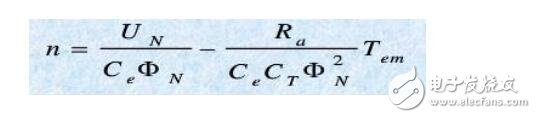
n is the speed of the motor, NU is the voltage at both ends of the motor, eC, TC, Nφ can be regarded as a fixed value for us, emT is the load torque, the value is basically determined after the car is completed, and the remaining one The important parameter is the resistance value of the aR motor armature circuit. The internal resistance of the motor itself is very small. If the externally introduced resistance is too large, the DC motor speed drops greatly, the drive circuit efficiency is low, and the motor performance cannot be fully exerted. In order to increase the speed of the motor, we should try to reduce the resistance of the motor armature loop winding. We know that the N-channel MOSFET has a very low on-resistance, the IRF3205 has an on-resistance of about 8m?, and the IRF4905 is almost two. Double, then can you consider using the N-channel 3205 to build our driver circuit? The answer is yes, but you need to change a gate driver chip!
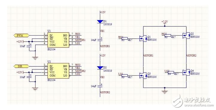
Here I am introducing IR's IR2104, because IR is known as the leader of power semiconductors, of course 2104 is relatively cheap! IR2104 can drive two high-side and low-side N-channel MOSFETs, which can provide larger gates. Drive current, and has hardware dead zone, hardware anti-arm conduction and other functions. A complete DC motor H-bridge driver circuit can be constructed using two IR2104 half-bridge driver chips. But need 12V drive!
IR2104 basic application circuit:
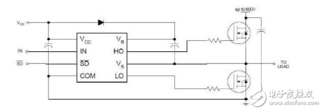
An enable signal for the SD signal is similar to the INH signal input terminal of the previous BTS. The active level is active and the chip operates. When IN is high, HO is high, LO is low, and when IN is low, HO is low. LO is high!
About the choice of key parameters:
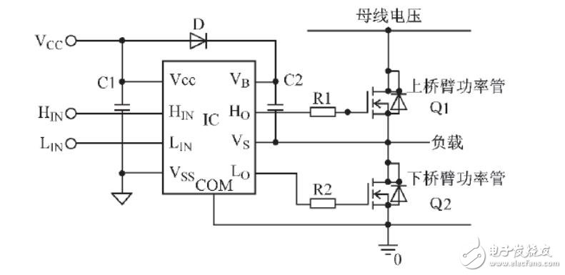
This driver design is easier to understand from the logic analysis of the signal. However, for in-depth understanding and better application, it is necessary to make a more in-depth analysis of the circuit and to make theoretical analysis and calculation of the parameters of some peripheral components. The IC in the figure is a high voltage driver chip that drives a half bridge MOSFET. Vb, Vs is the high-voltage end supply; Ho is the high-voltage end drive output; COM is the low-voltage end drive Power Supply, Lo is the low-voltage end drive output; Vss is the digital circuit power supply. The upper and lower bridge arms of the half-bridge circuit are alternately turned on, each When the lower arm is opened, the potential of the Vs pin is the saturation conduction voltage drop of the lower arm power tube Q2 when the upper arm is turned off, and is substantially close to the ground potential. At this time, Vcc charges the bootstrap capacitor C2 through the bootstrap diode D. It is close to the Vcc voltage. When Q2 is turned off, the voltage at the Vs terminal will rise. Since the voltage across the capacitor cannot be abrupt, the level of the Vb terminal is close to the sum of the voltages of the Vs and Vcc terminals, and the voltage between Vb and Vs is still close to the Vcc voltage. When Q2 is turned on, C2 acts as a floating voltage source to drive Q2; and the charge lost by C2 during Q2 turn-on is supplemented in the next cycle. This bootstrap mode is to use the level of Vs between high and low levels. It is the cheapest because the bootstrap circuit does not require a floating power supply. As shown in the figure, the bootstrap circuit charges a capacitor. The voltage on the capacitor floats up and down based on the source voltage of the high-side output transistor. D and C2 in the figure are the components that IR2104 should be carefully selected and designed in pulse width modulation (PWM) applications, and calculated and analyzed according to certain rules; and adjusted during circuit experiments to make the circuit work in an optimal state. Where D is an important bootstrap device, it should be able to block the high voltage on the DC mains. The current it receives is the product of the gate charge and the switching frequency. In order to reduce the charge loss, a fast recovery diode with a small reverse leakage current should be selected. The power supply in the high voltage part of the chip comes from the charge on the bootstrap capacitor C2 in the figure; in order to ensure that the high voltage part of the circuit has sufficient energy supply, the size of C2 should be appropriately selected.
For reference to the circuit, the parameters of which refer to the North University of Technology report:
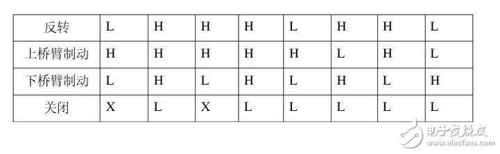
The principle of its work here is not to repeat the truth table that only provides its work, as follows:

IR2104 is cheaper, and rich students can study TD340 again. The basic principles are similar!
Toshiba has become one of the biggest selling for laptop in Europe, given the almost unprecedented success of the Toshiba Satellite range of laptops, the demand for the Toshiba Laptop Charger has increased dramatically.
Toshiba laptop charger includes Toshiba satellite charger series, toshiba Equium charger series, Toshiba Portege charger series, Toshiba Tecra charger series, and Toshiba Qosmio charger series, the mostly popular model is toshiba satellite laptop chargers.
The common Toshiba laptop charger specification has 30W 45W 60W, 90W 120W 180W 230W 19V, and 45W, 60W, 75W, 90W, 120W 15V etc, and the dc tip has common 5.5*2.5mm and 6.3*3.0mm with pin inside, round hole and round 4 pin etc. Also Yidashun has developed the 45W 5V/9V/15V/20V 3A/2.25A type c Adapter for Toshiba.
Yidashun can produce all models of Toshiba laptop adapter charger, and our laptop adapter with smart IC to protect your laptop with over current protection, over load protection, short circuit protection, over heat protection.
All our Toshiba laptop power adapter is Brand New Replacement Product, works as Genuine parts, 100% OEM Compatible!
")


Toshiba Laptop Charger,Toshiba Charger,Toshiba Satellite Charger,Toshiba Computer Charger
Shenzhen Yidashun Technology Co., Ltd. , https://www.ydsadapter.com