Design of wind-solar complementary LED lighting controller based on new substrate packaging technology
Abstract: This paper analyzes the characteristics of wind-solar complementary lighting system, and deeply discusses and studies the existing problems of various wind-solar complementary lighting controllers, and proposes a wind-solar complementary LED lighting control based on new substrate packaging. The design method of the device adopts novel circuit mode and special packaging method to effectively solve the brake fault problem existing in the existing wind-solar complementary lighting system and improve the reliability of the wind-solar complementary lighting system.
1 Introduction
At present, wind-solar complementary systems are developing rapidly, and there are many types of wind-solar complementary controllers, but there are not many systems that can achieve economical reliability, reliability and safety. One of the main reasons is that there is no good control. System. The wind-solar complementary lighting Controller works in the outdoor environment and is the core of the wind-solar complementary system. The technical requirements of the controller are high. Under the premise of satisfying the function, the control must be intelligent, reliable and long-lived. Good stability.
After the Battery is fully charged, the conventional photovoltaic controller will start the open circuit protection mode, disconnect the charging circuit of the Solar Panel and the battery, and protect the battery. However, for the wind and solar complementary lighting system, the fan cannot be used when the battery is overcharged. Direct open circuit protection, generally using the unloader to brake the fan.
In this paper, through in-depth study of the problems existing in the application of wind-solar complementary lighting system engineering, combined with years of practical experience, this paper proposes a design method of wind-solar complementary LED lighting controller based on new substrate package, which adopts novel circuit and special circuit packaging method. It solves the problem of brake failure in the existing wind-solar complementary lighting system and improves the reliability of the wind-solar complementary lighting system.
2 system composition
As shown in Figure 1, the wind-solar complementary lighting system consists of five parts: Wind Turbine, solar panel, battery, controller and unloader.
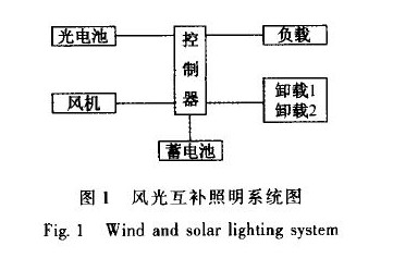
In the whole system, the functions of the controller mainly include the charge and discharge management of the battery, the on/off of the LED light and the full power/half power control. The charging and unloading control of the fan. The protection of the system hardware and software.
3 system design
3.1 Controller principle
The wind and solar hybrid controller is divided into control circuit and power circuit according to the function module, as shown in Figure 2.
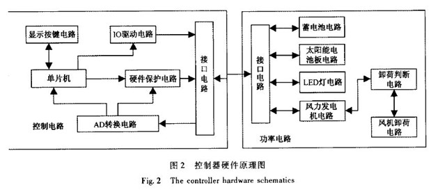
The control circuit includes a single chip microcomputer. AD conversion circuit. Display button circuit. 10 drive circuit. Hardware protection circuit and interface circuit; battery collected by power circuit board. Solar panel. LED lamp voltage and current signal are sent to AD conversion through interface circuit. The circuit and the AD conversion circuit convert the signal into a signal that can be recognized by the single-chip microcomputer, and send the single-chip microcomputer, and the single-chip computer processes the converted result, and then gives a control command, which is sent to the display button circuit and the IO driving circuit; the power circuit includes the battery circuit Solar panel circuit. LED lamp circuit. Wind turbine circuit. Unloading comparison circuit. Fan unloading circuit and interface circuit, external equipment battery. Solar panel. LED light is connected to battery circuit. Solar panel circuit and LED. The lamp circuit is sent to the unloading comparison circuit via the voltage signal outputted by the wind turbine circuit, and is compared by the unloading comparison circuit, and a control command is issued to the fan unloading circuit.
3.2 conventional unloading control method
In the wind-solar complementary lighting system, when the battery is overcharged or the wind speed is too high, the fan needs to be braked. The common protection control method is to collect the output voltage of the fan through the controller AD conversion circuit, and determine the fan unloading through the single limit comparison circuit. Whether or not.
As shown in Figure 3, Vcc-Wind.GND-Wind is the output of the fan after rectification, LM393D is the comparison chip, 2 feet is the comparator input voltage terminal. 3 feet input the fan through the voltage divider resistor R23.R24 The voltage is input to the 3 pin. The TVS is the voltage regulator. The anti-shock diode and the CIO are the filter capacitors. By comparing the voltage after the fan is rectified, the gated model Gate Shunt output is high and low level to control whether to unload.
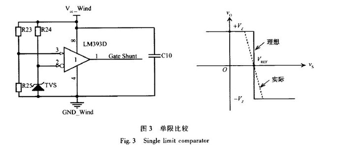
As shown in Figure 3, the single-limit comparator is very sensitive. Ideally, when the input voltage of the comparator reaches the reference voltage, the comparator switches the output state. However, in actual cases, the wind energy is random, and the generated voltage is intermittent. The switching characteristics are non-linear, which will result in a flat switching state of the comparator, and the anti-interference ability is relatively poor.
At this time, the MOS switch tube that controls the fan unloading is in a conducting and semi-conducting state, and the MOS is easily burned, causing damage to the controller.
3.3 New unloading control method
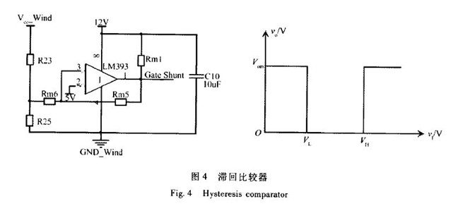
As shown in Figure 4, according to the poor anti-interference ability of the single-limit comparator in Figure 3, we introduce the hysteresis comparison circuit. The output pin 1 is fed back to pin 3, and the output characteristics of the circuit are in two threshold intervals. The unloading function is switched between two threshold points in the interval. The working state is not frequently switched, the stability of the comparator is improved, and thus the anti-interference ability is obtained. 12V is the supply voltage of the comparator, and RMl is the output end. Pull-up resistor, R23.R25 is the voltage divider resistor, pin 2 is the reference voltage.
Through long-term testing and engineering applications, the unloading pre-judging system using the hysteresis comparison circuit can perfect the protection of the internal switching components of the controller, and the stability of the unloading performance is high, achieving the requirements of practical engineering applications.
4 substrate packaging technology
Feeded to pin 3, the output characteristics of the circuit are in two threshold intervals, and the unloading function is switched between the two threshold points in this interval. The working state is not frequently switched, and the stability of the comparator is improved, thus having a certain The anti-interference ability. 12V is the comparator's power supply voltage, RMl is the output pull-up resistor, R23.R25 is the voltage divider resistor, and pin 2 is the reference voltage.
Through long-term testing and engineering applications, the unloading pre-judging system using the hysteresis comparison circuit can perfect the protection of the internal switching components of the controller, and the stability of the unloading performance is high, achieving the requirements of practical engineering applications.
In the wind-solar complementary lighting system, a large amount of energy is converted during charging of the battery by the solar power generator. A part of the energy is consumed by the heat energy, which poses a great risk to the stability of the system circuit, especially In the hot summer, the outdoor temperature reaches 40 degrees. When the controller performs power conversion or fan unloading, it will generate a lot of heat. If it cannot be dissipated in time, the internal electronic components of the controller will change with the temperature rise. Causes the controller to burn out.
Through the controller circuit design specifications, the independent innovation is designed into an aluminum substrate package circuit board. Its unique metal aluminum plate has good thermal conductivity. Electrical insulation performance and machining performance. When the wind speed is high, the controller power is too large. The heat can withstand the impact of high current and high temperature cycle, so that the wind and solar hybrid controller has high reliability, low cost and low power consumption.
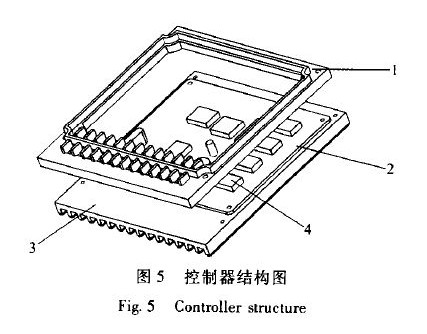
As shown in FIG. 5, the outside of the controller is mainly composed of an outer casing 1. an aluminum substrate 2 and a heat sink 3. The aluminum substrate 2 is located at the bottom of the outer casing 1, and the heat sink 3 and the aluminum substrate 2 are closely attached together. the aluminum substrate 2 and the heat sink The 3-phase contact surface is coated with thermal grease, which can withstand high current and high temperature impact. The controller power circuit is directly soldered on the aluminum substrate, and the aluminum substrate is connected with the heat sink to facilitate heat dissipation.
Through long-term testing and engineering applications, the wind-solar complementary controller packaged with aluminum substrate is 10 times more heat-dissipating than the general controller, which can quickly dissipate heat and protect the controller.
5 Conclusion
The wind-solar complementary LED lighting controller of the new substrate package solves the damage caused by the overspeed of the wind turbine through the new substrate packaging technology and the access function of the intelligent unloading module. This solution solves the overspeed braking of the wind turbine on one hand. Brake. Rapid heat dissipation, on the other hand, also improve wind energy, solar power reliability and power quality.
At the same time, the control system can realize the control of the power flow, so as to achieve a certain degree of peak-shaving and valley filling, which not only alleviates the contradiction of power consumption, but also improves the power supply structure of the power grid.
When the grid is cut off, the three-phase dump load of the controller will automatically start to work and the Inverter will stop output to grid. When the grid resuming, the controller stops three-phase dump load and the inverter will resume power supply.
The inside of the controller is equipped with surge protector. Contain the over voltage into the wind turbine under the bearable voltage of the equipment or system. On another way, to conduct the strong lightening current into the earth directly to avoid any damage of equipment.
On-grid Wind Solar Hybrid Controller
On-Grid Wind Solar Hybrid Controller,Automatic Controller,Solar Panel Street Light Controller,On-Grid Hybrid Controller
Delight Eco Energy Supplies Co., Ltd. , https://www.cndelight.com